In industrial automation and modern electronic systems, proximity sensors are indispensable components. They detect the presence or absence of an object without physical contact, enabling precise control in machinery, robotics, and safety systems. However, when a proximity sensor begins to malfunction, it can lead to unexpected downtime, production errors, or even safety hazards. Understanding the common causes of proximity sensor failure, how to diagnose issues, and implement effective solutions is crucial for maintaining operational efficiency.
A proximity sensor operates by emitting an electromagnetic field or a beam of electromagnetic radiation and looking for changes in the field or return signal. The most common types are inductive (for detecting metals), capacitive (for detecting both metals and non-metals), and photoelectric sensors. Anomalies typically manifest as false triggering, failure to detect an object, inconsistent detection ranges, or a complete lack of output signal.
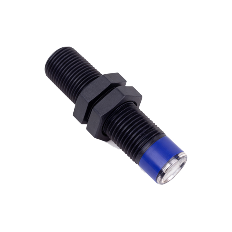
Several root causes can lead to these sensor abnormalities. Environmental factors are primary culprits. For inductive sensors, the accumulation of metallic dust or swarf on the sensing face can create a false shield, causing the sensor to trigger prematurely or not release. For capacitive sensors, changes in humidity, temperature, or the presence of contaminants like oil or coolant can alter the dielectric constant the sensor measures, leading to erratic behavior. Photoelectric sensors are highly susceptible to ambient light interference, dirt on the lens, or misalignment.
Electrical issues are another major category. Voltage spikes or surges on the supply line can damage the sensor's internal circuitry. Incorrect wiring, such as reverse polarity or loose connections, will prevent proper operation. Using a sensor with a load (like a relay or PLC input) that exceeds its maximum current rating can also cause failure over time. Furthermore, electrical noise from nearby motors, variable frequency drives (VFDs), or welding equipment can induce false signals in the sensor's output.
Mechanical problems should not be overlooked. Physical damage to the sensor housing or sensing face from impacts can destroy it. Vibration can loosen mounting hardware, causing misalignment. Over time, the internal components of any sensor can degrade due to normal wear and thermal cycling.
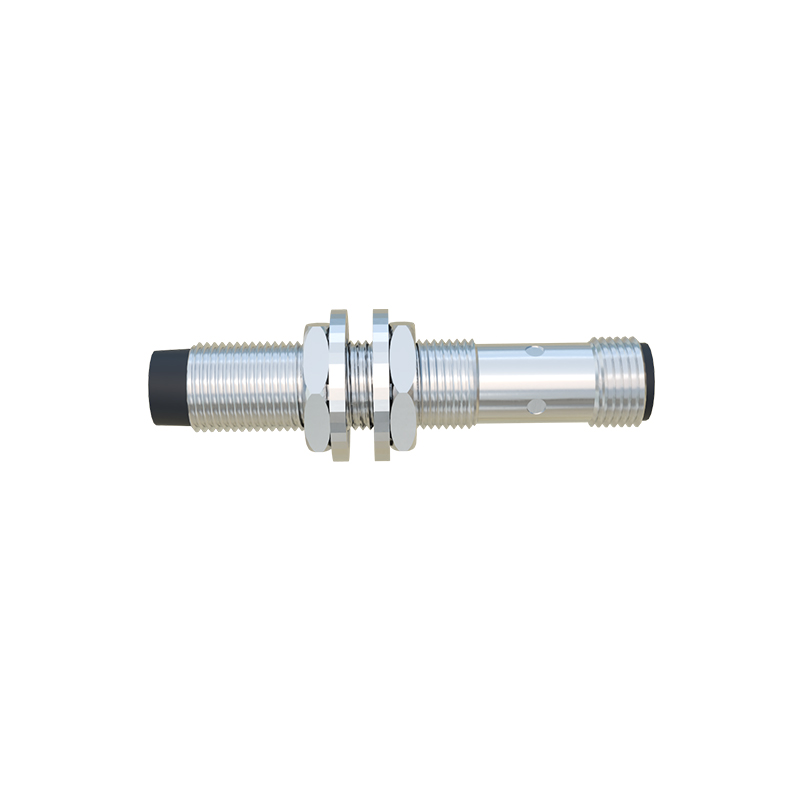
Diagnosing a suspected proximity sensor anomaly requires a systematic approach. Begin with a visual inspection. Check for obvious physical damage, contamination on the sensing face, and secure mounting. Verify the wiring against the datasheet for correct connections to power, ground, and the load. Next, use a multimeter to check the supply voltage at the sensor's terminals to ensure it is within the specified range (e.g., 10-30 VDC for many models).
To test the sensor's output, a reliable method is to monitor its state with the multimeter or a simple indicator like an LED test light. For a normally open (NO) sensor, the output voltage should be near supply voltage when no target is present and drop to near zero (or vice-versa for a PNP/NPN configuration) when a valid target is brought within the specified sensing range. Inconsistency in this behavior points to a faulty sensor. For photoelectric sensors, cleaning the lens and checking for alignment with the receiver or reflector is essential.
Implementing solutions depends on the diagnosed cause. For environmental issues, select a sensor with an appropriate Ingress Protection (IP) rating for the environment. Use sensors with built-in protection against washdown, chemicals, or extreme temperatures. Installing protective baffles or shrouds can shield sensors from flying debris. Regular cleaning schedules are a simple yet effective preventive measure.
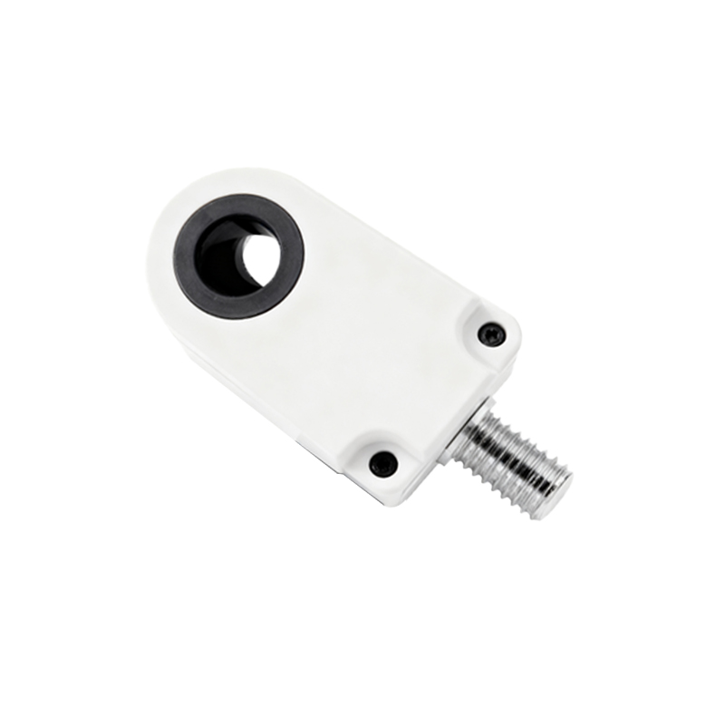
To combat electrical problems, ensure proper power supply conditioning. Use surge suppressors and shielded cables, grounding the shield at only one end to drain noise. Maintain a safe distance between sensor cables and high-noise power lines. Always use the correct sensor type for the application—for instance, a noise-immune model in areas with heavy electrical interference.
For mechanical reliability, ensure sensors are mounted securely using appropriate brackets. In high-vibration areas, consider sensors with robust, all-metal housings. Adhere to the specified sensing distance, typically aiming for 80% of the rated range to account for variations in target material or environmental conditions.
Proactive maintenance is the best defense against unexpected failures. This includes periodic inspection, cleaning, and functional testing. Keeping a log of sensor performance and failures can help identify recurring issues in specific locations or applications, guiding future sensor selection or system redesign. By understanding the vulnerabilities of proximity sensors and adopting a disciplined approach to diagnostics and maintenance, engineers and technicians can minimize disruptions and ensure the smooth, reliable operation of automated systems.