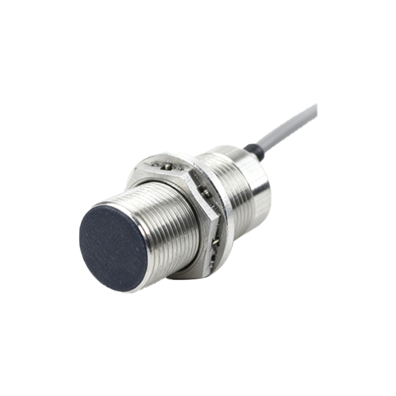
Inductive proximity sensors are non-contact electronic devices that detect the presence of metallic objects without physical contact. These sensors operate based on the principle of electromagnetic induction, making them highly reliable for industrial automation, position sensing, and safety applications. The core of an inductive proximity sensor consists of four main components: an oscillator circuit, a coil (inductor), a detection circuit, and an output switching stage.
At the heart of the sensor lies an LC oscillator circuit, where "L" represents the inductance of the coil and "C" denotes a capacitor. This oscillator generates a high-frequency alternating magnetic field around the active face of the sensor. When a metallic target enters this electromagnetic field, eddy currents are induced on the surface of the target. These eddy currents draw energy from the oscillator, causing a reduction in oscillation amplitude. The detection circuit continuously monitors the oscillator's amplitude. Once the amplitude drops below a predetermined threshold—indicating the presence of a metal object—the detection circuit triggers the output stage.
The output stage typically employs solid-state switches like transistors or integrated circuits to provide a clean, bounce-free signal. Common output configurations include NPN (sinking) or PNP (sourcing) transistor outputs, analog voltage/current outputs for distance measurement, and even IO-Link digital communication interfaces in advanced models. A key advantage of inductive sensors is their robustness. Since the sensing element is encapsulated, they are resistant to dust, moisture, oils, and mechanical wear, unlike mechanical limit switches.
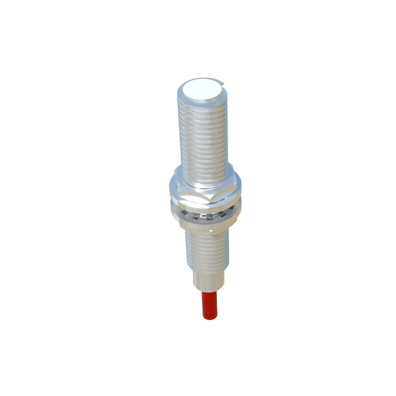
Designing the sensor coil is critical. The coil is usually wound on a ferrite core to concentrate the magnetic field, enhancing sensitivity and range. The effective sensing distance depends on factors like coil size, oscillator frequency (typically 100 kHz to 1 MHz), and the target material's properties. Ferrous metals like steel and iron cause a greater reduction in amplitude and can be detected at longer ranges compared to non-ferrous metals like aluminum or copper. This is quantified by a "reduction factor" specified in sensor datasheets.
Modern inductive proximity circuits incorporate several smart features. Temperature compensation circuits maintain stable performance across varying environmental conditions. Shielding is another crucial design aspect. Shielded (flush-mountable) sensors have a metal ring surrounding the coil, focusing the field forward and allowing installation flush with metal surfaces without false triggering. Unshielded (non-flush) sensors offer longer ranges but require a metal-free zone around them.
Applications are vast, from counting metal parts on a conveyor and detecting piston position in cylinders to ensuring machine door closure for operator safety. When integrating these sensors, engineers must consider the sensing distance, target size and material, electrical requirements (voltage, current, output type), and environmental factors like temperature and potential electrical interference. Proper installation, ensuring a stable power supply, and avoiding parallel runs of sensor cables with high-power lines are essential for noise immunity.
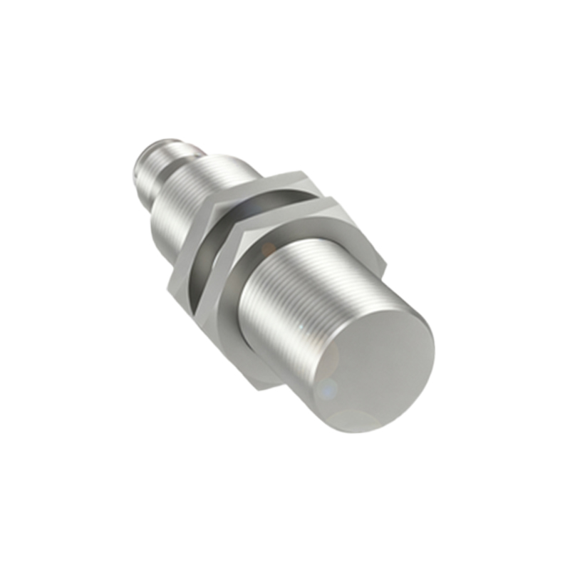
In summary, the inductive proximity sensor circuit elegantly transforms a physical phenomenon—eddy current generation—into a precise, reliable electrical signal. Its non-contact nature, durability, and versatility cement its role as a fundamental component in modern industrial control systems. Continuous advancements in integrated circuit technology are leading to sensors with smaller sizes, longer ranges, and embedded diagnostic capabilities, further expanding their utility in the era of Industry 4.0.