In the realm of industrial automation and process control, proximity temperature sensors represent a critical fusion of non-contact sensing and thermal measurement. While the term "proximity sensor" often conjures images of inductive or capacitive devices detecting metallic or non-metallic objects, the integration of infrared (IR) thermopile or pyroelectric sensing elements creates a specialized category: sensors capable of gauging temperature from a distance without physical contact. This article delves into the technical aspects of these devices, with a focus on the visual and functional characteristics evident in their imaging and design.
A typical proximity temperature sensor image reveals a compact, often cylindrical or rectangular housing, designed for robustness in harsh industrial environments. The front lens, usually made of germanium, zinc selenide, or other IR-transparent materials, is a key visual identifier. This lens is imperative for focusing infrared radiation emitted by the target onto the internal sensing element. High-quality images often showcase the sensor's field of view (FOV), depicted as a conical projection, which is crucial for application engineering. Engineers must match the sensor's FOV, visible in cutaway diagrams, to the target size to ensure accurate temperature readings and avoid background interference.
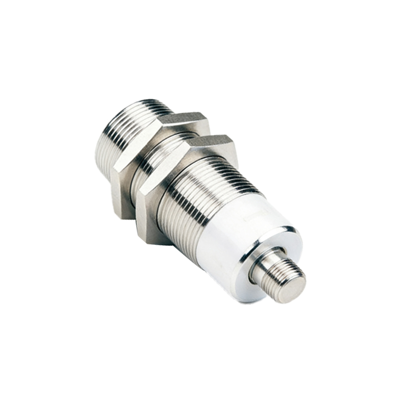
Internal schematic images are particularly instructive. They typically illustrate the arrangement of the IR detector (thermopile), signal conditioning circuitry, and the proximity sensing module—which may operate on ultrasonic, capacitive, or photoelectric principles. The convergence of these two data streams—distance and infrared radiation intensity—enables the device to provide a compensated temperature reading. Some advanced models feature integrated laser sighting, visible as a small red dot in promotional images, which precisely indicates the measurement spot, a feature highly valued in maintenance and troubleshooting scenarios.
The electrical connection interface is another detail captured in product images. Many proximity temperature sensors offer various output options, such as analog (4-20mA, 0-10V) or digital (IO-Link, Modbus), with connectors like M8 or M12 coded connectors being industry standards. These visual cues immediately inform an engineer about the sensor's compatibility with existing control systems. Furthermore, images highlighting the sensor's mounting—be it threaded barrels (e.g., M18, M30), flange mounts, or bracket systems—provide essential installation information. Proper mounting, as shown in application photos, is vital to maintain the correct sensing distance and avoid thermal shocks from the mounting surface itself.
Application-specific imagery demonstrates their versatility. In automotive manufacturing, images show these sensors monitoring brake disc temperature during testing. In food processing, they are pictured above conveyor belts, ensuring proper cooking or cooling temperatures without contaminating the product. In plastic extrusion, close-up photos depict sensors pointed at molten polymer, with thermal images sometimes superimposed to illustrate the correlation between the sensor's single-point reading and the actual thermal profile. These contextual images help engineers visualize integration points.
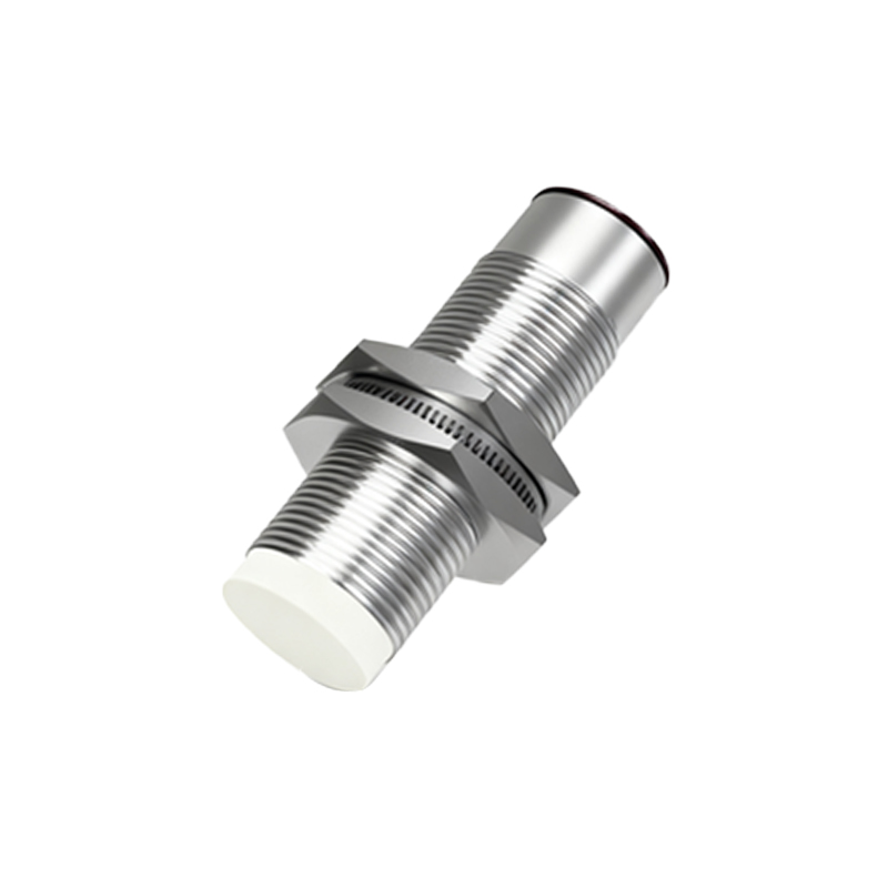
When evaluating proximity temperature sensors from datasheets or catalogs, key performance graphs are as important as product photos. Plots of response time versus distance, or temperature accuracy across the declared sensing range, provide the quantitative data needed for selection. An image of the sensor's environmental rating, often indicated by an IP67 or IP69K marking on the housing, communicates its resilience to dust and water ingress—a non-negotiable feature in washdown areas or foundries.
In conclusion, for the practicing engineer, proximity temperature sensor images are far more than marketing visuals. They are dense with technical information: the lens material hints at the spectral response; the housing design suggests the environmental robustness; the connection type dictates network integration; and application photos inspire solution design. A thorough analysis of these images, coupled with specification sheets, is fundamental to selecting the right sensor for precise, reliable, and non-contact temperature monitoring in dynamic industrial settings. The ability to interpret these visual details separates a functional installation from an optimized, high-performance one.