Proximity sensors are critical components in modern industrial automation, enabling non-contact detection of objects within a defined range. As an electrical engineer, understanding how to properly test these sensors ensures system reliability, minimizes downtime, and maintains operational safety. This guide outlines systematic methods for testing inductive, capacitive, and ultrasonic proximity sensors, tailored to industry standards.
First, always begin with a visual inspection. Check the sensor housing for physical damage, corrosion, or contamination. Ensure the mounting is secure and aligned correctly, as misalignment can cause false readings. Verify that the wiring connections are tight and that cables are free from cuts or abrasions. For sensors in harsh environments, inspect seals for integrity to prevent ingress of dust or moisture.
Next, use a multimeter to measure electrical parameters. Disconnect the sensor from the control system if possible to avoid backfeed. For DC sensors, set the multimeter to voltage mode. Apply power according to the datasheet specifications—typically 10-30V DC. Measure the output voltage between the signal wire and ground. In the absence of a target, the output should be low (near 0V for NPN types or supply voltage for PNP). Introduce a valid target within the sensing range; the output should switch states. For example, an NPN normally-open sensor should show a voltage close to the supply when activated.
For AC sensors, use caution due to higher voltages. Employ a true-RMS multimeter to measure output voltage. Ensure the target material matches the sensor type—inductive sensors detect metals, while capacitive sensors respond to both conductive and non-conductive materials. If the output does not change, the sensor may be faulty or the target may be outside its effective range.
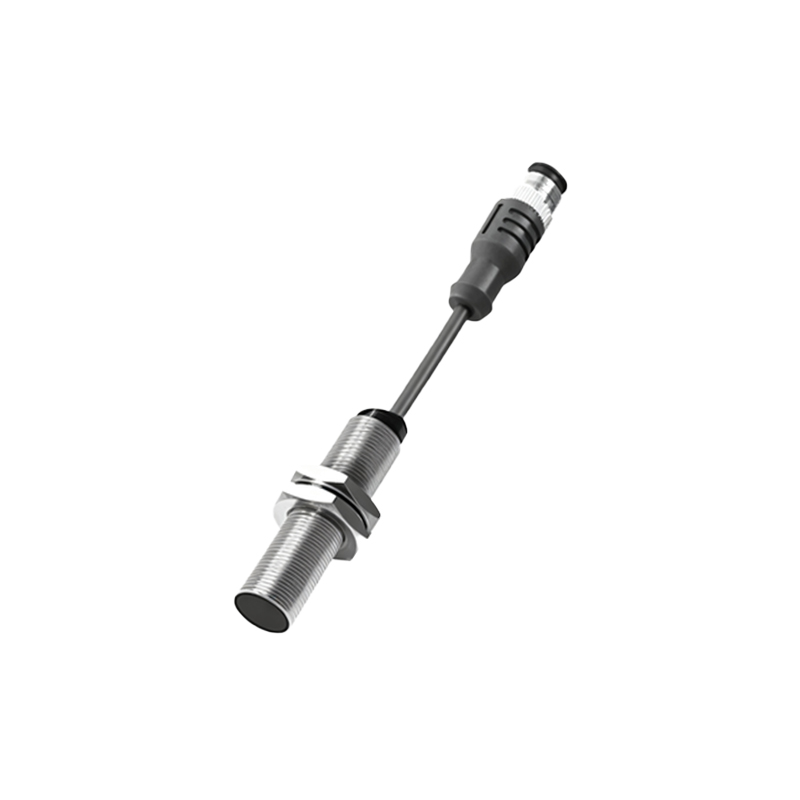
Oscilloscopes provide deeper diagnostics. Connect the probe to the output terminal to observe switching characteristics. Look for clean transitions without excessive noise or bounce. Delayed response times can indicate internal component degradation. Compare the observed signal with the timing diagrams in the manufacturer’s datasheet. For analog output sensors, verify that the output current (e.g., 4-20 mA) scales linearly with distance. Any deviation suggests calibration issues.
Functional testing under real conditions is essential. Simulate the operational environment by moving a standard target toward the sensor at the rated speed. Measure the maximum sensing distance—this should match the datasheet value within tolerance. Repeat tests with different target sizes and materials to ensure consistency. For ultrasonic sensors, test with various surface textures, as rough materials can scatter sound waves and reduce accuracy.
Temperature and environmental factors can affect performance. Use a thermal chamber or controlled setting to test sensors at extreme temperatures specified in the datasheet. Inductive sensors may lose sensitivity in high heat, while capacitive sensors can drift with humidity changes. Record any deviations and adjust mounting or shielding accordingly.
Finally, integrate the sensor with the PLC or controller. Monitor input status lights or software diagnostics to confirm proper communication. Use diagnostic tools like ladder logic or SCADA systems to log sensor events over time, identifying intermittent faults. Replace sensors that fail any test phase, and always document results for maintenance records.
Regular testing schedules prevent unexpected failures. Establish baseline performance metrics during installation and compare periodic tests against them. Training personnel on these methods enhances troubleshooting efficiency and supports continuous improvement in automation systems. By following these steps, engineers can ensure proximity sensors operate reliably, contributing to optimized production lines and reduced operational risks.