In the realm of electrical engineering and industrial automation, laser vision sensors have emerged as indispensable tools for non-contact, high-precision measurement and inspection. Their ability to capture detailed 3D profiles and surface data with exceptional speed and accuracy makes them critical for quality control, robotic guidance, and dimensional analysis. The core of leveraging these sophisticated devices lies in accurate sensor modeling, which mathematically describes the relationship between the physical world coordinates and the sensor's acquired image data. This article delves into the fundamental principles and methodologies for modeling laser vision sensors, focusing on the prevalent structured-light triangulation technique.
A typical laser vision sensor system comprises three primary components: a laser line projector, a camera (typically a CCD or CMOS sensor), and a processing unit. The laser projector emits a thin, focused plane of light onto the target object's surface. This line becomes deformed according to the object's contour. The camera, positioned at a known angle relative to the laser plane, captures this deformed line. The core task of sensor modeling is to establish a precise mapping function that converts the 2D pixel coordinates (u, v) of the laser line in the camera image into 3D world coordinates (X, Y, Z).
The modeling process generally involves two main stages: camera calibration and laser plane calibration. Camera calibration is a well-established procedure to determine the intrinsic and extrinsic parameters of the camera. Intrinsic parameters include the focal length, principal point coordinates, and lens distortion coefficients (both radial and tangential). These parameters define the internal geometry and optical characteristics of the camera. The widely adopted pinhole camera model, often enhanced with distortion models, serves as the foundation. Extrinsic parameters define the camera's position and orientation (rotation and translation) in the world coordinate system. Techniques using calibration patterns, such as checkerboards, are standard for this purpose, solving for parameters using methods like the Direct Linear Transform (DLT) or non-linear optimization algorithms.
Following camera calibration, the critical step is calibrating the laser plane. The laser plane is defined in the world coordinate system. The goal is to determine its equation, typically expressed as Ax + By + Cz + D = 0. A common and effective method involves using a planar target with a known, precise surface (e.g., a high-grade calibration plate). The target is placed at several known positions along the Z-axis (height). At each position, the sensor captures the laser line projected onto the target. For each captured line image, a set of 3D points on the target surface corresponding to the laser stripe is known from the target's known geometry and position. By combining these known 3D points with their corresponding 2D image coordinates from the calibrated camera, one can solve for the parameters (A, B, C, D) of the laser plane equation using least-squares fitting. This process effectively "teaches" the system the exact spatial orientation of the light plane.
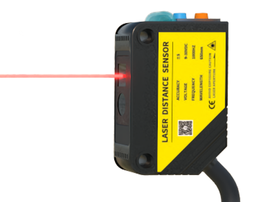
Once both models are established, the 3D coordinate calculation for any new measurement point becomes a geometric triangulation problem. For a given pixel (u, v) on the laser line in a new image, a ray in 3D space is projected from the camera's optical center through that pixel point, using the inverse of the camera's projection model. The 3D coordinate of the measured point is the intersection of this projected ray with the calibrated laser plane. This intersection calculation is performed in real-time by the sensor's processor for every point along the laser line, generating a dense cloud of 3D profile data.
Advanced modeling considerations must account for several real-world factors to maintain sub-micron or micron-level accuracy. These include thermal effects that alter component dimensions, vibrations, ambient light interference, and the optical properties of the target surface (e.g., reflectivity, translucency, color). For highly reflective or dark surfaces, the laser line intensity profile can distort, affecting the centerline extraction algorithm's accuracy—a crucial step before coordinate transformation. Some sophisticated models incorporate sub-pixel interpolation techniques for line extraction and may even model the laser's intensity distribution.
In practical electrical engineering applications, such as inspecting printed circuit board (PCB) solder paste height, measuring component coplanarity, or guiding robots for wire harness assembly, a robust and accurately modeled laser vision sensor is paramount. The model not only enables precise measurement but also allows for sensor fusion within larger coordinate systems, such as robotic arms or multi-sensor inspection stations. Regular re-calibration, guided by the established model parameters, is essential for long-term measurement integrity.
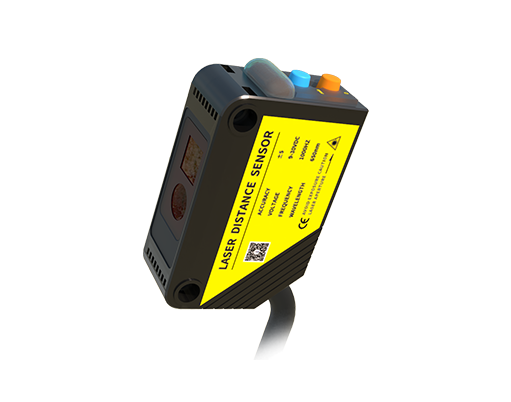
In conclusion, the mathematical modeling of laser vision sensors is a rigorous yet essential engineering discipline. It transforms a system of optical and electronic components into a reliable quantitative measurement instrument. By meticulously calibrating the camera and laser plane parameters, engineers can unlock the full potential of these sensors, ensuring the high precision required in modern automated manufacturing, electronics assembly, and a vast array of industrial metrology tasks. Continued research focuses on self-calibrating models, multi-line laser systems for full-field scanning, and enhanced models to cope with complex surface finishes, pushing the boundaries of non-contact measurement technology.