Proximity sensors are critical components in modern industrial automation, enabling non-contact detection of objects and ensuring seamless operation of machinery. Over time, these sensors may degrade due to environmental factors, mechanical wear, or electrical issues, necessitating replacement. This guide provides a comprehensive, industry-standard procedure for safely and effectively replacing proximity sensors in industrial settings.
Before initiating any replacement, ensure compliance with safety protocols. De-energize the equipment by locking out and tagging out (LOTO) the power source to prevent accidental activation. Verify the absence of voltage using a multimeter. Wear appropriate personal protective equipment (PPE), including insulated gloves and safety glasses.
Identify the faulty sensor by reviewing system diagnostics or observing operational failures, such as inconsistent detection or complete non-responsiveness. Note the sensor’s specifications: type (inductive, capacitive, or magnetic), sensing range, output configuration (PNP/NPN), voltage rating, and connection interface. Document the wiring scheme with photographs or diagrams to facilitate reinstallation.
Disconnect the sensor from the control system. For wired sensors, loosen the cable gland or connector, and carefully detach the wires, labeling each terminal (e.g., brown for +V, blue for 0V, black for signal). For modular sensors with quick-disconnect fittings, release the locking mechanism and separate the sensor from the base. Remove the sensor from its mounting bracket using suitable tools, such as hex keys or wrenches, taking care not to damage adjacent components.
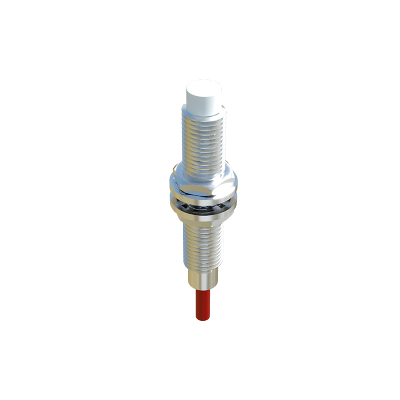
Select a replacement sensor matching the original specifications. Cross-reference part numbers or consult manufacturer datasheets to ensure compatibility. Inspect the new sensor for damage and confirm its sensing range and output type align with application requirements. If upgrading, verify that the new model integrates with existing control logic and mechanical interfaces.
Mount the new sensor in the original position, aligning it precisely to maintain the correct sensing orientation and distance. Tighten mounting hardware to the manufacturer’s recommended torque to avoid vibration-induced misalignment. Reconnect the wiring according to your documentation, ensuring secure terminations and proper cable strain relief. For connectors, verify positive engagement and lock the fitting.
Restore power and conduct functional tests. Gradually energize the system and observe the sensor’s indicator LED (if present) for normal operation. Use a test object within the sensing range to verify detection consistency. Monitor the control panel or PLC for accurate signal reception. Perform calibration if required, adjusting sensitivity or timing parameters per the manual.
Document the replacement by updating maintenance records, including the date, sensor model, and any adjustments made. This aids future troubleshooting and inventory management. Regularly inspect sensors for contamination, corrosion, or physical damage to preempt failures. Implement preventive maintenance schedules based on operational hours or environmental conditions.
By following this methodical approach, engineers can minimize downtime, enhance system reliability, and extend equipment lifespan. Always prioritize safety and refer to OEM guidelines for model-specific nuances.