Proximity sensors are indispensable components in modern industrial automation, providing non-contact detection of objects for applications ranging from assembly line positioning to safety interlocks. However, their accuracy and reliability are not inherent; they are the direct result of proper installation and meticulous calibration. A poorly calibrated sensor can lead to false triggers, missed detections, and costly production downtime. This guide details the systematic process for calibrating inductive, capacitive, and ultrasonic proximity sensors to ensure they operate within their specified parameters.
The calibration process begins long before adjusting any settings. First, ensure the sensor is correctly installed according to the manufacturer's specifications. Verify the mounting, ensuring it is secure and free from excessive vibration. Check the electrical connections for the power supply and output wiring, confirming voltage levels and polarity. For inductive sensors, the target material must be considered, as the sensing distance (the nominal range) is typically specified for mild steel. For other materials like aluminum, brass, or stainless steel, a reduction factor must be applied, effectively reducing the usable sensing range. Capacitive sensors are influenced by the target material's density and dielectric constant, while ultrasonic sensors can be affected by temperature, humidity, and air turbulence.
The core of calibration involves setting the sensor's sensitivity or threshold to detect the target object reliably at the desired distance while ignoring background interference. Follow these general steps:
1. Establish a Reference: Use the specified standard target (e.g., a square of mild steel of defined dimensions for inductive sensors). Position this target at the exact nominal sensing distance (Sn) listed on the sensor's datasheet.
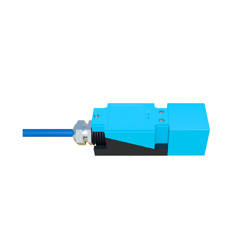
2. Power On and Observe: Apply the correct operating voltage to the sensor. Most sensors have an LED indicator that signals power and output state.
3. Adjust Sensitivity: Many modern sensors feature a potentiometer or teach-in function for calibration. For a potentiometer-based sensor:
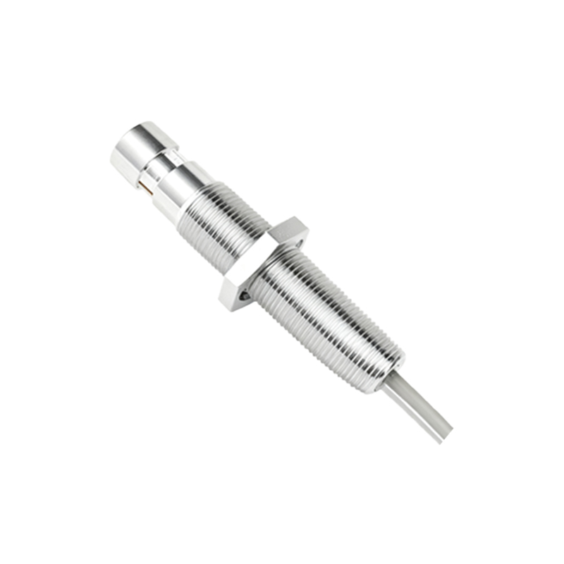
With the reference target at the nominal distance, slowly rotate the adjustment screw.
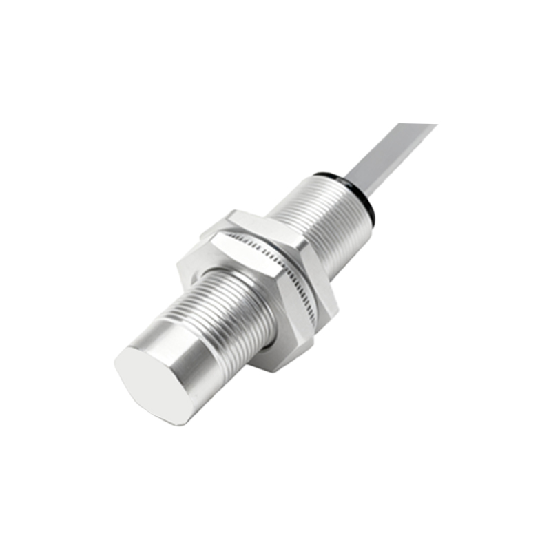
Turn the screw until the output LED just activates (or deactivates, depending on the logic—NO or NC). Then, rotate it slightly further (typically 1/8 to 1/4 turn) into the operating range to provide a safety margin. This margin accounts for minor variations in target position, temperature drift, and supply voltage fluctuations.
4. Test the Range: After setting the sensitivity with the reference target, verify the sensor's performance across its entire required operating range. Move the target toward and away from the sensor face. Note the point where the output switches. This is the actual sensing point. It should be consistent and repeatable. For applications requiring precise positioning, this point must be stable.
5. Test with Interference: A critical step often overlooked is testing for false triggers. For inductive sensors, bring non-target metals (like the machine frame or other actuators) near the sensor's lateral sides to ensure they do not cause activation. For capacitive sensors, which detect any material, changes in humidity or nearby containers can cause drift; shield the sensor from such environmental noise. For ultrasonic sensors, test for echoes from nearby stationary objects.
6. Document Settings: Once optimal settings are found, document the potentiometer position or, for programmable sensors, save the configuration. This is vital for future maintenance and troubleshooting.
For advanced sensors with IO-Link or other digital interfaces, calibration is often more precise and repeatable. Using configuration software, you can set parameters like switching hysteresis, response time, and temperature compensation digitally. The teach-in function can be executed via a software command or a physical button, storing the exact sensing distance into memory. This eliminates the guesswork associated with analog potentiometers.
Regular verification is part of a robust calibration regimen. Environmental factors such as temperature extremes, accumulation of metallic dust on inductive sensor faces, or oil/coolant film on capacitive sensors can degrade performance over time. Schedule periodic checks where the reference target is presented to the sensor, and the output is verified. Any deviation beyond acceptable tolerances warrants re-calibration.
In summary, effective proximity sensor calibration is a methodical blend of understanding sensor technology, following a structured adjustment procedure, and implementing ongoing verification. It transforms a simple detection device into a reliable and precise component of a complex control system. Investing time in proper calibration minimizes unexpected failures, enhances product quality, and maximizes overall equipment effectiveness (OEE) on the factory floor.