Proximity switch sensors are essential components in modern industrial automation, widely used for position detection, object counting, and safety applications. The wiring head, a critical interface between the sensor and the control system, ensures reliable signal transmission and power supply. Proper installation and maintenance of the wiring head are vital for optimal sensor performance and system longevity. This article provides a comprehensive guide to proximity switch sensor wiring heads, covering types, installation steps, troubleshooting, and industry best practices.
Types of Proximity Switch Wiring Heads:
Wiring heads for proximity switches typically come in two main configurations: pre-wired connectors and screw terminal types. Pre-wired connectors, such as M8 or M12 connectors, offer quick installation and are ideal for applications requiring frequent sensor replacement. They feature standardized pin assignments: brown wire for DC positive (+), blue wire for DC negative (-), and black wire for the output signal. Screw terminal wiring heads, on the other hand, allow direct wire connection and are preferred for permanent installations where flexibility is less critical. Both types must match the sensor's electrical specifications, including voltage rating (commonly 10-30V DC) and output type (PNP or NPN).
Installation Procedure:
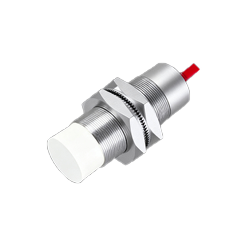
1. Power Off: Always disconnect power to the system before beginning installation to prevent electrical hazards or damage to components.
2. Sensor Preparation: Identify the wiring head type compatible with your proximity switch. For pre-wired connectors, align the connector with the sensor's port and secure it by tightening the locking mechanism. For screw terminal heads, strip the insulation from the wires (typically 6-8 mm) and insert them into the appropriate terminals, ensuring tight connections to avoid loose contacts.
3. Wiring Connection: Connect the wires to the control system according to the sensor's datasheet. For DC sensors, the brown wire goes to positive voltage, blue to negative, and black to the input module (e.g., PLC). Shielded cables are recommended in environments with electromagnetic interference (EMI) to reduce noise.
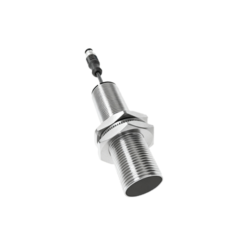
4. Testing: After installation, restore power and test the sensor by bringing a target object within its sensing range. Verify the output signal using a multimeter or indicator light to ensure proper operation.
Common Issues and Troubleshooting:
- Intermittent Signals: Often caused by loose wiring or poor connections. Check all terminal screws and connectors for tightness.
- No Output: Confirm power supply voltage and polarity. Incorrect wiring (e.g., reversed polarity) can damage the sensor. Inspect for damaged cables or faulty wiring heads.
- False Triggering: May result from environmental factors like metal debris or EMI. Ensure proper grounding and use shielded cables. Adjust the sensor's sensitivity if applicable.
Best Practices for Maintenance:
- Regular Inspection: Periodically check wiring heads for signs of wear, corrosion, or loose connections, especially in harsh conditions (e.g., high humidity or vibration).
- Environmental Protection: Use IP-rated wiring heads (e.g., IP67) for dust and water resistance in outdoor or washdown applications.
- Documentation: Label wires and maintain wiring diagrams to simplify future maintenance or modifications.
In summary, the wiring head is a key element in proximity switch sensor systems, impacting reliability and efficiency. By selecting the appropriate type, following correct installation steps, and adhering to maintenance guidelines, engineers can minimize downtime and enhance operational safety. As automation evolves, staying updated with industry standards, such as IEC 60947-5-2 for proximity devices, ensures compatibility and performance in diverse applications.