Elco laser sensors are widely recognized in industrial automation for their precision, reliability, and versatility in tasks such as distance measurement, object detection, and positioning. Proper calibration and debugging are critical to ensuring these sensors perform optimally within complex systems. This guide provides a systematic approach to configuring, calibrating, and troubleshooting Elco laser sensors, adhering to professional engineering standards.
The initial phase involves pre-installation verification. Before mounting, confirm the sensor model specifications align with the application requirements, including measuring range, resolution, output type (analog, digital, or serial interface), and environmental ratings (IP protection, temperature tolerance). Inspect the sensor and cable for physical damage. Ensure the power supply voltage matches the sensor's input requirements; incorrect voltage is a common cause of immediate failure or erratic behavior.
Mounting the sensor correctly is foundational. The sensor must be securely fixed to minimize vibration, which can introduce noise into measurements. Alignment is paramount: the laser beam should be perpendicular to the target surface for distance measurement applications. For edge detection or contour profiling, the angle must be precisely set as per the technical manual. Avoid mounting near strong ambient light sources or reflective surfaces that could interfere with the laser signal. Maintaining a stable temperature environment, away from excessive heat sources, is also recommended to prevent thermal drift.
Following physical installation, proceed with electrical connection and basic power-on. Connect the output wires to the appropriate controller input (e.g., PLC, data acquisition card). Apply power and observe the sensor's indicator LEDs. A steady power LED typically indicates normal operation, while blinking patterns often signal specific statuses or errors—consult the datasheet for exact codes. At this stage, avoid having any object within the measuring range to check for a "no target" signal state.
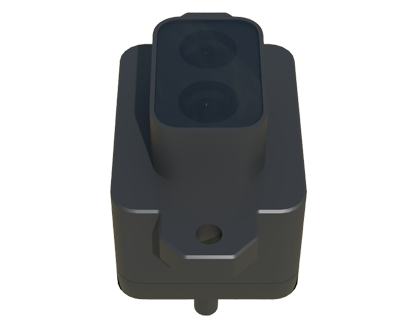
Calibration is the core of sensor setup. Most Elco laser sensors feature teach-in functions or software-configurable parameters. The primary steps generally include:
1. Reference Distance Setting: Place a target at a known, precise reference distance within the sensor's range. Using the teach button or configuration software, set this point as the zero or span reference. For analog output sensors, this defines the 0V/4mA and 10V/20mA points corresponding to the minimum and maximum measurement limits.
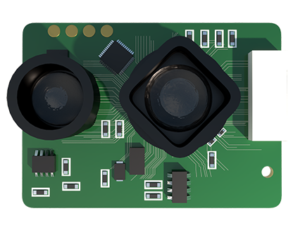
2. Output Characteristic Configuration: Define the output response. Choose between linear, logarithmic, or window comparator modes based on the application. For binary detection, set the switching threshold and hysteresis to prevent signal chatter when an object is near the detection limit.
3. Filter and Response Time Adjustment: Configure averaging filters to smooth out signal noise from environmental vibrations or surface irregularities. Adjust the sensor's response time to match the process speed; too fast may cause instability, while too slow introduces lag.
4. Parameter Storage: Once configured, store the parameters in the sensor's non-volatile memory. Some advanced models allow profile storage for multiple application setups.
Debugging and troubleshooting follow a logical sequence. If the sensor exhibits inaccurate readings or fails to detect objects, begin with these checks:
* Signal Verification: Use an oscilloscope or multimeter to monitor the raw output signal. Compare it against expected values. Noise on the output line may indicate grounding issues or electromagnetic interference (EMI). Ensure proper shielding and grounding of the sensor body and cable.
* Target Property Check: Laser sensor accuracy is influenced by target color, surface texture, and material. Dark, absorbent, or transparent materials may return a weak signal. Highly reflective or glossy surfaces can cause saturation or multiple reflections. Adjust the sensor's sensitivity or use a retro-reflective foil on problematic surfaces.
* Environmental Interference: Intense ambient light, dust, fog, or oil mist can scatter or overpower the laser beam. Verify the sensor's operating environment is within its specified limits. Protective air curtains or enclosures may be necessary in harsh conditions.
* Software Diagnostics: Connect the sensor to Elco's proprietary configuration software (if applicable). This interface provides detailed diagnostic information, real-time signal visualization, and advanced parameter tuning not available via hardware buttons.
* Cross-Verification: Validate the sensor's reading with a manual measurement tool (e.g., caliper, micrometer) at multiple known points to identify any non-linearity or offset errors.
For persistent communication issues with network-enabled Elco sensors, verify the baud rate, node address, and protocol settings (e.g., PROFINET, EtherNet/IP, RS-485) against the host controller's configuration. A faulty cable or connector is often the culprit for intermittent failures and should be swapped for testing.
Regular maintenance ensures long-term stability. Periodically clean the sensor lens with a soft, lint-free cloth to remove dust or contaminants. Re-verify calibration at scheduled intervals, especially after significant environmental changes or mechanical shocks to the system. Keep a log of calibration dates and parameter sets for traceability.
In summary, effective Elco laser sensor integration hinges on meticulous installation, methodical calibration tailored to the specific use case, and structured troubleshooting. By understanding the interplay between the sensor's settings, the target properties, and the operating environment, engineers can unlock the full potential of these devices, enhancing system accuracy, reliability, and productivity. Always prioritize consulting the official Elco technical documentation for model-specific instructions and safety guidelines.