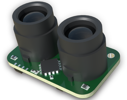
Eddy current thickness sensors represent a critical category of non-contact measurement devices widely employed in industrial quality control and process monitoring. Their operation is grounded in the principles of electromagnetic induction. At its core, the sensor generates a high-frequency alternating magnetic field via an excitation coil. When this field interacts with a conductive target material, such as aluminum, copper, or steel, it induces circular electrical currents—known as eddy currents—within the material. These eddy currents, in turn, generate their own opposing magnetic field, which interacts with the sensor's primary field. The sensor's electronics precisely measure the change in the coil's impedance, which is directly correlated to the distance between the sensor probe and the target, i.e., the material's thickness, provided the material's electrical conductivity and magnetic permeability are known and consistent.
The advantages of this technology are manifold. Primarily, it enables high-precision, non-contact measurement, which is indispensable for applications involving hot, moving, delicate, or coated surfaces where physical contact is impractical or damaging. Measurement is instantaneous and does not require coupling mediums, making it ideal for high-speed production lines. Typical industrial applications are diverse. In metal rolling mills, these sensors provide real-time thickness feedback for strip steel or aluminum, enabling precise gauge control. They are used to measure the thickness of critical components in aerospace manufacturing, such as turbine blades and fuselage skins. In the automotive sector, they verify paint or coating thickness on car bodies. Furthermore, they play a role in monitoring wear on machinery components like bearing races or verifying the thickness of semiconductor wafers and various conductive films.
However, the performance of an eddy current sensor is not absolute; it is influenced by several material and environmental factors. The most significant are the electrical conductivity and magnetic permeability of the target material. A sensor calibrated for non-ferrous aluminum will yield inaccurate readings if used on ferrous steel without recalibration due to the stark difference in permeability. Temperature fluctuations can affect both the sensor's electronics and the target material's properties, potentially introducing drift. Therefore, many modern sensors incorporate temperature compensation circuits. The target's geometry also matters; very small or curved surfaces can distort the eddy current field, affecting accuracy. Surface conditions, such as roughness, oxidation, or the presence of non-conductive coatings, must also be considered, as they alter the effective distance to the conductive base material.

Selecting the appropriate eddy current thickness sensor requires a meticulous analysis of the application parameters. Key specifications to evaluate include measurement range, resolution, linearity, and frequency response. The required range dictates the probe size and type. Resolution, often in the sub-micron range for high-end models, must meet the tolerance demands of the part. The sensor's output signal type—analog (e.g., 0-10V, 4-20mA) or digital (e.g., RS-485, Ethernet/IP)—must be compatible with the existing data acquisition or control system. Environmental robustness is crucial; probes and housings are rated with Ingress Protection (IP) codes for dust and water resistance, and must withstand ambient temperatures, potential coolant splash, or electromagnetic interference present on the factory floor. For applications involving non-conductive coatings on a conductive substrate, the sensor must be capable of "seeing through" the coating to measure the base metal thickness, a feature dependent on the operating frequency.
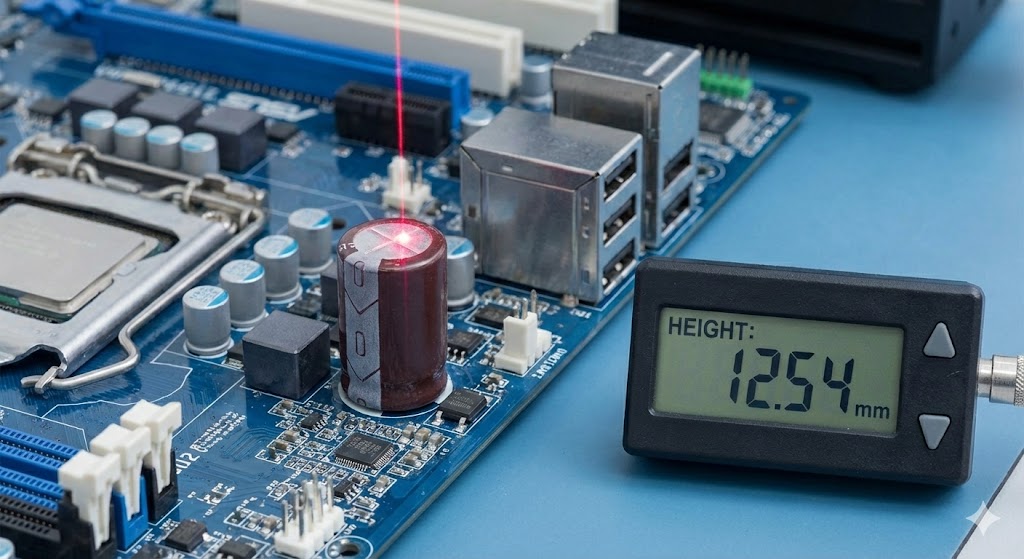
Installation and calibration are final, critical steps for ensuring optimal performance. Mechanical mounting must be rigid and vibration-free to prevent measurement noise. The probe must be positioned perpendicular to the target surface within the manufacturer's specified tolerance to avoid cosine error. Initial calibration involves using certified thickness standards made of the exact same material as the production target. Multi-point calibration across the expected thickness range establishes the sensor's characteristic curve, which is stored in the associated controller or software. Regular verification against calibration standards is necessary to maintain traceability and accuracy over time, as part of a comprehensive preventive maintenance program.
In conclusion, eddy current thickness sensors offer a reliable, high-speed solution for non-destructive thickness measurement of conductive materials. Their successful implementation hinges on a thorough understanding of the underlying electromagnetic principles, a careful assessment of the target material properties and application environment, and the precise selection and calibration of the sensor system. When deployed correctly, they become indispensable tools for enhancing product quality, optimizing material usage, and ensuring process stability in modern manufacturing.