In the realm of industrial automation and control systems, proximity sensors are indispensable components. Their primary function is to detect the presence or absence of an object without physical contact, offering reliability, longevity, and precision. However, a critical yet often overlooked specification is the sensor's load capacity or switching capacity. This parameter defines the maximum electrical load the sensor's output can safely handle, directly impacting system safety, longevity, and performance.
Fundamentally, the load capacity of a proximity sensor refers to the maximum current and voltage its output switching element can manage. This is not a measure of its sensing distance or accuracy, but of its electrical robustness in driving downstream components like relays, PLC (Programmable Logic Controller) inputs, solenoid valves, or indicator lamps. Exceeding this capacity is a primary cause of premature sensor failure, potentially leading to costly downtime.
Proximity sensors typically come with two main output types, each with distinct load characteristics:
1. Solid-State Outputs (Typically PNP or NPN Transistors): These are the most common in modern DC sensors. Their load capacity is defined by the maximum continuous current (e.g., 100mA, 200mA) and the maximum operating voltage (e.g., 30V DC). A key specification here is the "Residual Current" or "Leakage Current" when in the 'OFF' state. Even when switched off, a small current (usually microamps to a few milliamps) may flow. This leakage must be considered when connecting to highly sensitive PLC inputs, as it might be misinterpreted as an 'ON' signal. Conversely, the "Voltage Drop" in the 'ON' state (typically 1-2V) is the voltage lost across the sensor's internal transistor, reducing the voltage available to the load.
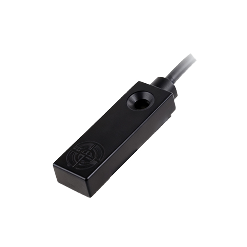
2. Electromechanical Relay Outputs: Some proximity sensors, or sensor-based relay units, incorporate an internal mechanical relay. These offer significantly higher load capacities, often capable of switching several amperes at 120V AC or 240V AC. They are ideal for directly controlling motors, heaters, or high-power solenoids. However, they have moving parts, which can wear out over time due to mechanical cycling and are generally slower than solid-state outputs.
Key Factors Influencing and Determining Load Capacity:
Output Configuration: As outlined above, relay outputs handle higher loads than transistor outputs.
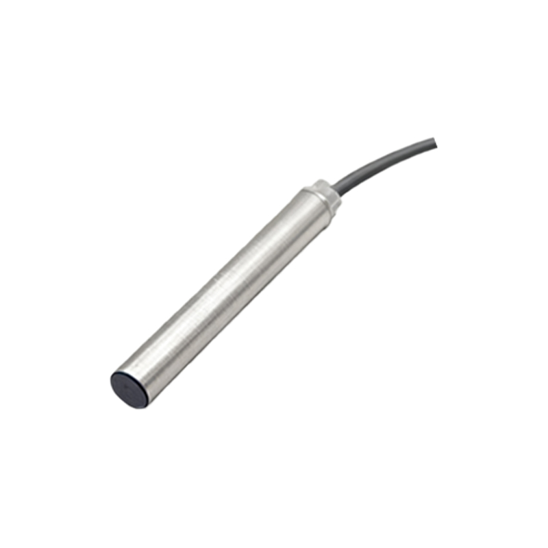
Circuit Protection: The load capacity rating assumes a purely resistive load. Inductive loads (like solenoids and relay coils) and capacitive loads generate voltage spikes (back-EMF) and inrush currents that can far exceed the sensor's rated capacity. Using protective components such as flyback diodes (for DC inductive loads), RC snubber circuits (for AC inductive loads), or varistors is essential to protect the sensor's output.
Duty Cycle and Ambient Temperature: The published load capacity is usually for a continuous current at a specified ambient temperature (e.g., 25°C). Operating in high-temperature environments or with pulsed loads requires derating—reducing the maximum usable current to prevent overheating of the internal semiconductor junction.
Connection to PLCs: When connecting a standard 3-wire DC proximity sensor to a PLC digital input module, compatibility is crucial. The sensor's output type (PNP sourcing vs. NPN sinking) must match the PLC input type. Furthermore, the PLC input's impedance and required "ON-state current" must be within the sensor's capability, while the sensor's "OFF-state leakage current" must be below the PLC's threshold to guarantee reliable switching.
Practical Application and Sizing Guidelines:
To correctly apply a proximity sensor, follow these steps:
1. Identify the Load: Determine the device the sensor will control. Note its type (resistive, inductive), operating voltage, and most importantly, its steady-state current draw and inrush current (if any).
2. Check Sensor Specifications: Consult the sensor's datasheet for its maximum switching current and voltage. Pay close attention to the conditions (temperature, load type) under which this rating is valid.
3. Apply a Safety Margin: It is a universal best practice to select a sensor whose continuous current rating is at least 1.5 to 2 times the load's normal operating current. This margin accounts for transient spikes, minor overloads, and ensures a long operational life.
4. Implement Protection: For inductive loads, always incorporate the appropriate suppression circuit as recommended by the sensor manufacturer.
5. Consider Interface Devices: If the load exceeds the sensor's capacity, use the sensor to drive an intermediate device with a suitable rating, such as an interposing