Laser proximity sensors are sophisticated devices widely utilized across industrial automation, robotics, and safety systems for precise non-contact detection. Their structural composition is meticulously engineered to ensure high accuracy, reliability, and adaptability in diverse operational environments. The core architecture of a typical laser proximity sensor can be dissected into several key functional modules: the laser emission unit, the optical system, the photodetector and signal processing unit, the housing and mechanical interface, and the output/communication interface.
The heart of the sensor is the Laser Emission Unit. This module typically employs a semiconductor laser diode, often operating in the visible red spectrum (e.g., 650nm) or infrared range. A key component here is the drive circuit, which provides stable, regulated current to the laser diode, ensuring consistent optical output power. Modern designs frequently incorporate modulation techniques, where the laser beam is pulsed at a specific high frequency. This modulation is crucial for enhancing immunity to ambient light interference and improving signal-to-noise ratio. The laser diode is mounted on a precise submount within a TO-can package, which also includes a monitor photodiode for real-time feedback on output power, enabling automatic power control (APC) circuits to maintain stability over temperature variations and lifetime.
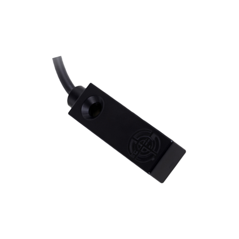
Following emission, the Optical System takes center stage. Its primary function is to shape, direct, and focus the raw laser beam. This system usually consists of collimating lenses, which convert the divergent beam from the diode into a parallel or slightly focused beam. For long-range or highly precise applications, additional focusing lenses are used to create a sharp, small-diameter spot on the target. The optical path also includes apertures or filters to define the beam profile and block unwanted wavelengths. A critical sub-component is the beam splitter or partially reflective mirror, which is essential in the optical design of many reflective-type sensors. It directs a portion of the emitted beam toward the target and allows the returning reflected light to pass through to the detector. The quality of these optical elements—their coatings, alignment, and material—directly impacts the sensor's spot size, range, and overall accuracy.
The returning light, either reflected from the target (in diffuse or retro-reflective models) or the interruption of the beam (in through-beam models), is captured by the Photodetector and Signal Processing Unit. A high-speed photodiode or, in more advanced sensors, a position-sensitive device (PSD) or CMOS/CCD array, acts as the receiver. The photodetector converts the faint optical signal into a corresponding electrical current. This minuscule signal is then fed into a transimpedance amplifier (TIA), the first stage of a sophisticated analog front-end. Subsequent stages involve filtering to isolate the modulated signal frequency from noise, followed by amplification. A demodulation circuit then extracts the envelope of the modulated signal. For distance measurement using triangulation or time-of-flight (ToF) principles, specialized processing circuits or embedded microcontrollers analyze the signal's phase shift, time delay, or spot position on the detector array. This processed data is compared against set thresholds to determine the presence, absence, or precise distance of an object.
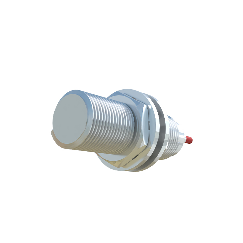
Encasing and protecting these delicate internal components is the Housing and Mechanical Interface. The housing is typically constructed from robust materials like nickel-plated brass, stainless steel, or industrial-grade plastics, offering protection against dust, moisture (often rated IP67 or higher), and mechanical shock. It provides precise mounting for the optical elements, ensuring permanent alignment. The front window is made of scratch-resistant glass or optical-grade plastic, sometimes with anti-reflective coatings. The mechanical design includes standardized mounting threads (e.g., M8, M12, M18, M30) or brackets for easy integration into machinery. Effective thermal management design, sometimes involving heat sinks, is integrated to dissipate heat from the laser diode and processing electronics, ensuring stable performance across the specified temperature range.
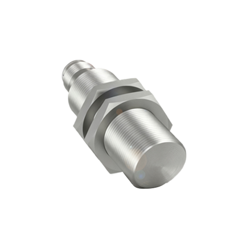
Finally, the Output and Communication Interface forms the sensor's connection to the wider control system. Traditional models provide discrete digital outputs (PNP/NPN transistors) or analog outputs (0-10V, 4-20mA) corresponding to detection status or measured distance. Modern intelligent sensors feature integrated microprocessors and offer advanced digital interfaces such as IO-Link, which enables bidirectional communication for parameter configuration, diagnostics, and process data transmission. Power is supplied typically via DC sources (10-30V DC), with protection circuits against reverse polarity and voltage spikes. Status indicators, usually LEDs, provide visual feedback for power, output state, and sometimes signal strength or fault conditions.
In summary, the laser proximity sensor is a marvel of optoelectronic integration. Each structural component, from the modulated laser source and precision optics to the high-sensitivity detector and ruggedized housing, plays a vital role in delivering the