In industrial automation, laser sensors are widely used for precise detection, measurement, and positioning tasks due to their high accuracy and reliability. Proper wiring is crucial to ensure optimal performance and prevent damage to the sensor or connected systems. This guide provides a step-by-step approach to wiring a laser sensor, covering key considerations for electrical connections, safety protocols, and troubleshooting common issues.
First, identify the sensor's specifications from its datasheet, including voltage requirements (typically 10-30 V DC for most industrial models), output type (e.g., NPN, PNP, or analog), and pin configuration. Most laser sensors feature a standard cable with color-coded wires: brown for positive voltage (+V), blue for negative or ground (0V), black for output signal, and white for additional functions like teach-in or diagnostics. Always disconnect power before starting wiring to avoid electrical hazards.
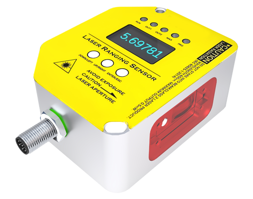
For basic wiring, connect the brown wire to the positive terminal of a DC power supply within the specified voltage range. The blue wire should be linked to the power supply's negative terminal and the system ground to minimize noise interference. The output wire (often black) connects to the input of a controller, such as a PLC or relay. If using an NPN output, wire it to the PLC's sinking input; for PNP, use a sourcing input. Ensure cables are routed away from high-voltage lines or motors to prevent electromagnetic interference, which can cause false triggers.
In applications requiring analog output (e.g., distance measurement), additional wires may be present for analog signals (e.g., gray for voltage output, pink for current output). Connect these to the appropriate analog input modules, following the sensor's manual for scaling settings. For sensors with teach-in or IO-Link capabilities, use designated wires for programming or data exchange, and verify compatibility with industrial networks.
After wiring, perform a functional test by applying power and observing the sensor's indicator LEDs. A steady green light typically indicates proper operation, while flashing lights may signal errors like misalignment or wiring faults. Use a multimeter to check voltage levels at connections if issues arise. Common problems include reversed polarity, loose terminals, or incorrect output loading—always double-check connections against the datasheet.
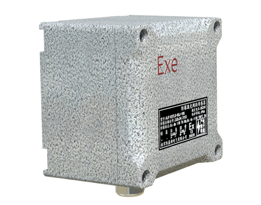
Finally, secure cables with cable ties or conduits to protect against physical damage and environmental factors like dust or moisture. Regular maintenance, including visual inspections and cleaning of the sensor lens, ensures long-term reliability. By following these guidelines, engineers can achieve stable and accurate laser sensor integration in systems ranging from packaging machinery to robotic assembly lines.