In industrial automation and precision measurement, laser sensors have become indispensable tools due to their high accuracy, non-contact operation, and rapid response times. Proper distance setting is a critical factor that directly impacts sensor performance, measurement reliability, and overall system efficiency. This article delves into the principles, methodologies, and best practices for optimizing laser sensor distance settings, tailored for engineers and technicians in the electrical and automation sectors.
Laser sensors operate primarily on triangulation or time-of-flight (ToF) principles. Triangulation-based sensors are ideal for short to medium ranges, typically up to a few meters, offering micron-level resolution. The optimal working distance here is determined by the baseline between the laser emitter and receiver, as well as the lens focal length. Deviating from the specified reference distance can cause defocusing, leading to signal degradation and increased measurement error. For ToF sensors, used for longer distances (often exceeding 10 meters), the key is ensuring sufficient signal return strength. The sensor must be positioned within its defined measurement range, where the emitted laser pulse has enough energy to reflect back to the detector without excessive attenuation.
The process of setting the correct distance begins with a thorough review of the sensor datasheet. Manufacturers specify a nominal or reference working distance, a measurement range, and often a diagram of the optical path. For triangulation sensors, the "standoff distance" is the precise gap from the sensor housing to the target surface at which the sensor is calibrated for peak performance. Engineers must account for target properties: highly reflective surfaces can saturate the receiver, while dark or absorptive materials may weaken the signal. In such cases, fine-tuning the distance—sometimes slightly closer or farther than the nominal value—can compensate for these material effects. Ambient light interference, particularly from other lasers or intense infrared sources, must also be mitigated, often by adjusting sensor orientation or using protective housings.
Practical calibration involves using a precision positioning stage to move the sensor relative to a calibration target. The sensor output (typically analog voltage or digital readings) is monitored to identify the distance that yields the most stable and linear response. For dynamic applications where the target distance varies, the sensor should be set at a midpoint within its measurement span to maximize headroom. Regular verification with certified gauge blocks or distance standards is essential to maintain calibration over time, especially in environments with temperature fluctuations that can affect optical components.
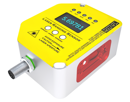
Integration into automated systems adds layers of complexity. Programmable logic controllers (PLCs) or dedicated sensor amplifiers often allow software-based offset and gain adjustments. These can digitally correct for minor distance misalignments without physical repositioning. However, physical optimization remains foundational. Safety is paramount: laser sensors, particularly Class 2 or higher, require adherence to safety standards such as IEC 60825, ensuring that installation distances prevent accidental eye exposure.
In summary, optimal laser sensor distance setting is a blend of understanding optical principles, meticulous hardware calibration, and adaptive software configuration. It ensures not only precise measurements but also enhances system robustness, reduces downtime, and extends sensor lifespan. As industrial applications evolve toward smarter, more interconnected systems, mastering these fundamental setup techniques remains a core competency for electrical engineers driving innovation in automation and quality control.