Laser displacement sensors are widely used in industrial automation, precision manufacturing, and quality control due to their non-contact measurement capabilities, high accuracy, and fast response times. However, like any measurement system, they are subject to various errors that can impact performance. Understanding these error sources is crucial for engineers to ensure reliable data and optimal system integration.
One primary source of error is environmental factors. Temperature fluctuations can cause thermal expansion or contraction in both the sensor housing and the target material, leading to drift in measurements. For instance, a sensor calibrated at 20°C may exhibit significant deviation if operating in a 40°C environment without compensation. Similarly, ambient light interference, especially from strong direct light sources like sunlight or certain industrial lamps, can saturate the sensor's detector, causing inaccurate readings. Dust, smoke, or vapor in the air can scatter or absorb the laser beam, attenuating the signal and introducing noise.
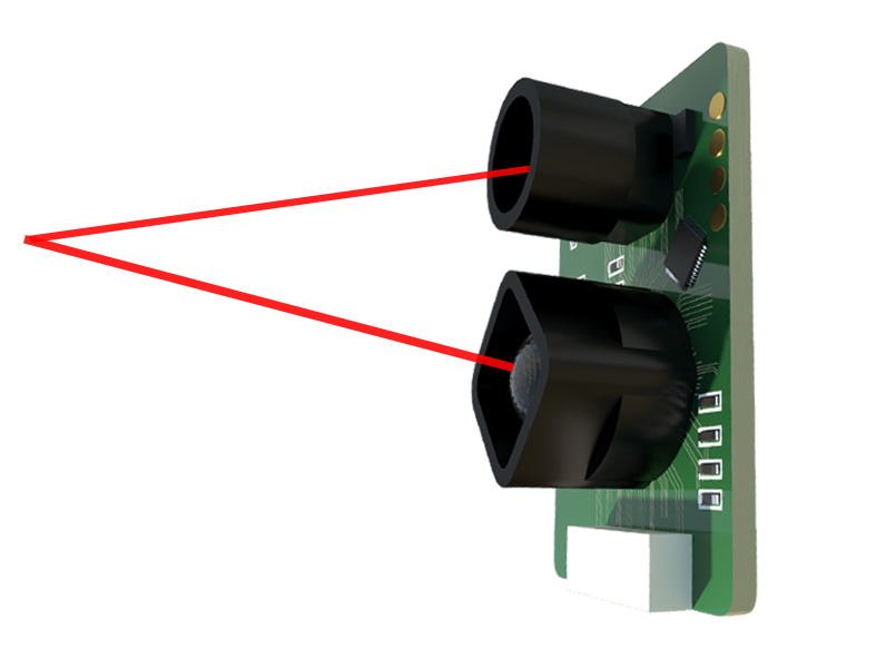
The target surface characteristics profoundly influence measurement accuracy. Ideally, laser sensors perform best on opaque, matte, and uniformly colored surfaces. Challenges arise with highly reflective or specular surfaces, as they can reflect the beam away from the detector, causing signal loss or "dropouts." Transparent or translucent materials, such as glass or clear plastics, allow the laser to penetrate, resulting in measurements of an internal layer rather than the intended surface. Rough or textured surfaces scatter the laser light, broadening the beam spot and potentially shifting the centroid detected by the sensor, leading to a phenomenon known as speckle noise. Even the color of the target matters; dark, low-reflectivity surfaces absorb more light, reducing the signal-to-noise ratio and potentially pushing it below the sensor's minimum required threshold.
Sensor-specific limitations constitute another critical error category. The inherent linearity error defines how much the sensor's output deviates from a perfectly straight line across its measurement range. This is typically specified in the datasheet as a percentage of the full scale. Resolution, the smallest detectable change, is limited by electronic noise and detector capabilities. High-speed measurements can be affected by the sensor's response time; if the target moves faster than the sensor can sample, data points will be missed or averaged incorrectly. The angle of incidence is also vital. Most sensors are calibrated for perpendicular measurement. If the laser beam strikes the target at an oblique angle, the measured distance will be longer than the true perpendicular distance, a geometric error that must be corrected mathematically in the application.
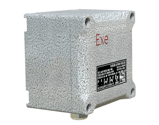
Electrical and installation errors are often overlooked. Noise from nearby motors, variable frequency drives, or high-current cables can be inductively or capacitively coupled into the sensor's signal lines, corrupting the analog output. Proper shielding and grounding are essential. Mechanical vibration of either the sensor or the target can introduce high-frequency jitter into the readings. Mounting stability is paramount; any looseness or deflection in the bracket will translate directly into measurement error. Furthermore, incorrect configuration of parameters like response time, averaging filters, or output scaling within the sensor's software can mask or even amplify underlying physical errors.

Mitigation strategies involve a systematic approach. First, select the right sensor for the application, considering range, spot size, and specialized models for difficult surfaces (e.g., models with coaxial illumination for shiny surfaces). Control the environment where possible: use enclosures for temperature stability, install light shrouds to block ambient light, and employ air knives or enclosures to keep the optical path clear of contaminants. Prepare the target surface if feasible; applying a matte coating or using a retro-reflective tape can standardize reflectivity. During installation, ensure rigid, vibration-free mounting and perfect alignment. Utilize the sensor's built-in features, such as temperature compensation, digital filtering, and programmable output conditioning. Finally, establish a robust calibration routine using traceable standards under conditions that mimic the actual operating environment as closely as possible. Regular verification checks are necessary to detect long-term drift or degradation.
In conclusion, while laser displacement sensors are powerful tools, their accuracy is not absolute. Errors stem from a complex interplay of environmental conditions, target properties, sensor limitations, and integration practices. By thoroughly analyzing the application scenario, proactively addressing potential error sources, and implementing rigorous calibration and maintenance procedures, engineers can significantly mitigate these errors, thereby unlocking the full potential of laser sensor technology for demanding precision measurement tasks.