In the realm of industrial automation and control systems, proximity sensors are indispensable components. While commercial options are plentiful, designing and building a DIY proximity sensor switch offers invaluable insights into electromagnetic theory, circuit design, and practical implementation. This guide is tailored for electrical engineers and seasoned hobbyists seeking to deepen their understanding through hands-on creation.
A proximity sensor detects the presence or absence of a nearby object without physical contact, typically using electromagnetic fields, light, or sound. For this DIY project, we will focus on constructing an inductive proximity sensor, ideal for detecting metallic objects. The core principle is based on Eddy currents. A high-frequency oscillating circuit generates an electromagnetic field from a coil. When a metallic object enters this field, Eddy currents are induced within the object, causing a measurable change in the oscillation amplitude or frequency within the sensor's coil circuit.
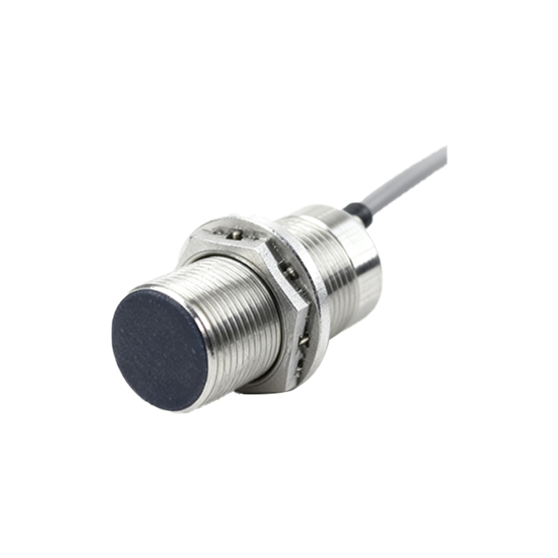
The primary components required are:
1. Oscillator Circuit: This forms the heart of the sensor. A simple yet effective design utilizes a Colpitts or Hartley oscillator configuration, often built around a transistor like the 2N2222 or an operational amplifier (op-amp) such as the LM358. The oscillator generates a stable high-frequency signal (typically between 100 kHz to 1 MHz) through an LC tank circuit.
2. Sensing Coil (Inductor): This is the transducer. It can be a custom-wound air-core coil or a ferrite-core inductor. The number of turns, coil diameter, and core material directly affect sensitivity and sensing range. For prototyping, a 50-100 turn coil wound on a small ferrite rod is effective.
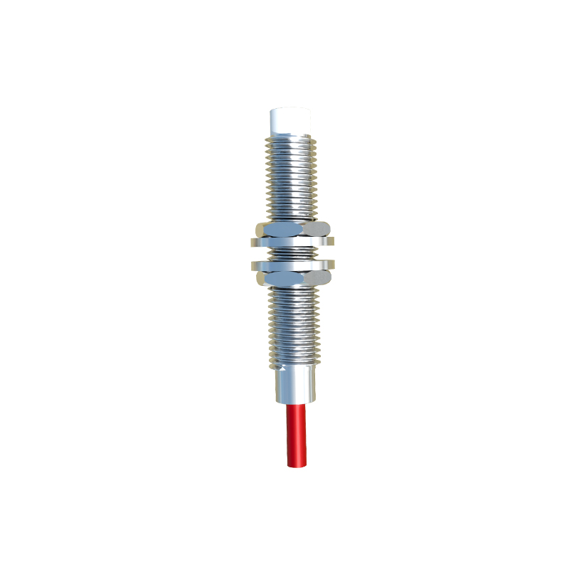
3. Detection/Demodulation Stage: This circuit monitors the oscillator's output. As a metal object dampens the oscillation, this stage converts the change in amplitude into a DC voltage shift. A diode detector (using a Schottky diode like 1N5817) followed by a smoothing capacitor is a classic approach.
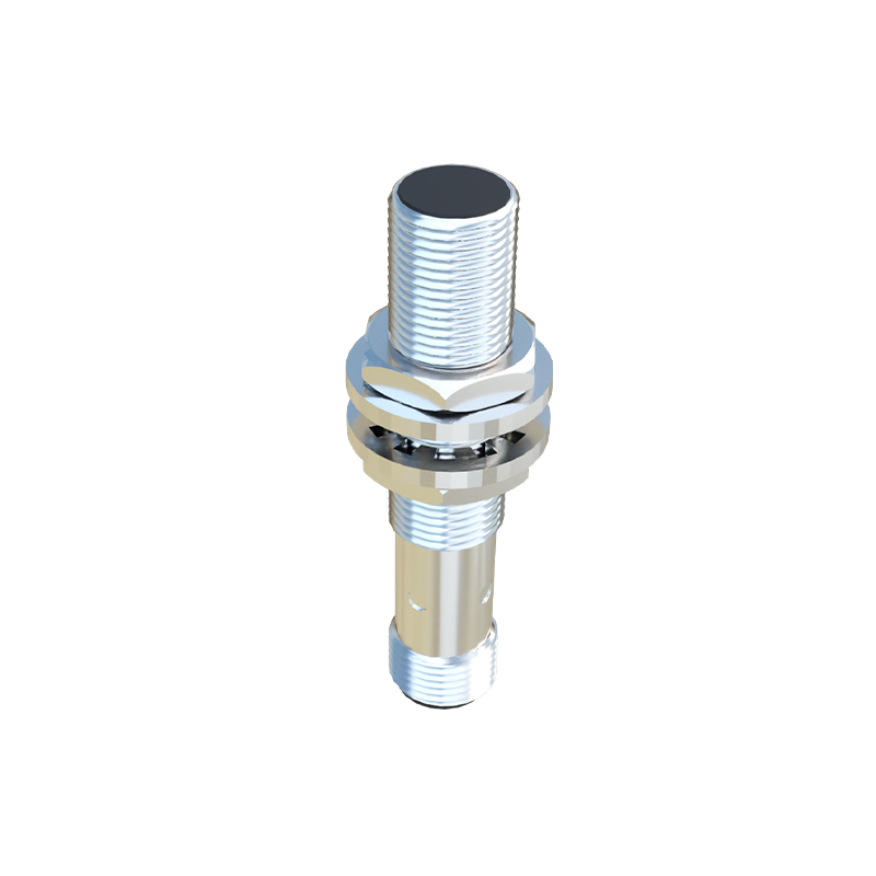
4. Trigger/Schmitt Trigger: The raw DC signal from the detector is often noisy. A Schmitt trigger circuit (using an op-amp or a dedicated IC like the 74HC14) cleans the signal, providing a sharp, digital ON/OFF output with hysteresis to prevent chatter.
5. Output Stage: This interfaces with your control system. For a simple switch, a transistor (e.g., a BC547 for low current or a MOSFET like IRF540 for higher loads) can be used to drive a relay or an optocoupler, providing isolation and the ability to control AC/DC loads.
Construction Steps:
1. Design the Oscillator: On a breadboard or PCB, assemble the oscillator circuit. Ensure proper decoupling with capacitors (e.g., 100nF ceramic) near the active components' power pins to ensure stable oscillation. Connect the sensing coil as part of the LC tank.
2. Wind the Coil: Carefully wind your chosen gauge of enameled copper wire around a form. Secure the windings with tape or varnish. Measure its inductance with an LCR meter if available; this helps in tuning the oscillator frequency.
3. Integrate the Detector: Connect the output from the oscillator tank to the diode detector. The resistor and capacitor values in this network will determine the response time. A typical RC time constant of 1-10ms is a good starting point.
4. Add the Schmitt Trigger: Feed the detector's DC output into the Schmitt trigger. Adjust the resistor divider network to set the precise switching threshold for your desired sensing distance.
5. Implement the Output: Connect the Schmitt trigger's clean digital signal to the base/gate of your output transistor. Connect the relay or load in the collector/drain circuit. Always include a flyback diode across an inductive load (like a relay coil) to protect the transistor.
6. Power Supply: Use a stable, regulated DC power source (e.g., 12V). Incorporate voltage regulators (like 78L05) if different circuit sections require different voltages.
Calibration and Testing:
Power the circuit and use an oscilloscope to observe the oscillator waveform. Bring a metal target (e.g., a steel wrench) close to the coil. You should see a change in amplitude or frequency. Adjust the potentiometer in the Schmitt trigger's feedback loop to fine-tune the sensitivity—the distance at which the output reliably switches. Test with different metals (aluminum, copper, steel) as their conductivity and permeability affect detection range.
Key Considerations:
Shielding: The coil is susceptible to external electromagnetic interference. Consider shielding it with a metal can (open on the sensing face) to improve directionality and stability.
Environmental Factors: