Two-wire proximity sensors are widely used in industrial automation due to their simplicity and cost-effectiveness. Unlike three-wire or four-wire sensors, they integrate the switching element and power supply into a single circuit, making installation straightforward but requiring careful consideration of electrical parameters. This guide provides a step-by-step approach to wiring two-wire proximity sensors, ensuring reliable operation in various applications.
First, understand the basic principle. A two-wire proximity sensor operates similarly to a switch in series with the load. It requires a power supply (typically 10-30V DC) and connects directly to the load (e.g., a PLC input, relay, or indicator). The sensor draws a small leakage current (usually under 1.5 mA) when off, which must be below the threshold of the connected device to avoid false triggering. When activated, it allows full current flow to the load.
Before wiring, always review the sensor datasheet. Key specifications include operating voltage, current rating, leakage current, and output type (normally open or normally closed). Ensure compatibility with your power supply and load. For example, if using a 24V DC supply, verify the sensor supports this range. Also, check the load's minimum operating current—some PLC inputs require at least 3 mA, which may not be met by certain sensors in the off state.
Wiring steps are as follows:
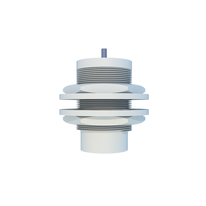
1. Power Off: Disconnect all power sources to prevent electrical shock or damage.
2. Identify Wires: Two-wire sensors have two leads, often color-coded (e.g., brown for positive, blue for negative). Refer to the manufacturer's labeling.
3. Connect to Power Supply: Link the positive wire (brown) to the DC positive terminal and the negative wire (blue) to the DC negative terminal. Ensure polarity is correct to avoid malfunction.
4. Integrate the Load: Place the load in series with the sensor. For a normally open sensor, the circuit closes when a target is detected. Connect one sensor wire to the power supply and the other to the load, then link the load's remaining terminal to the power supply's opposite pole. This forms a complete loop.
5. Secure Connections: Use appropriate terminals or connectors to prevent loose wires, which can cause intermittent failures.
6. Test the System: Apply power and bring a target (e.g., metal object) within the sensing range. Verify the load activates as expected. Measure voltage and current to confirm they fall within specified limits.
Common pitfalls include ignoring leakage current. If the load's minimum current is too high, the sensor may not switch off completely, leading to residual activation. To mitigate this, add a bypass resistor in parallel with the load to shunt excess current. Calculate the resistor value using Ohm's law based on the supply voltage and required current. For instance, with a 24V supply and a 2 mA leakage, a 12 kΩ resistor can help dissipate unwanted current.
Another issue is voltage drop. Two-wire sensors have an internal voltage drop (typically 2-4V), reducing the voltage available to the load. Ensure the load can operate at the lower voltage. For long cable runs, consider voltage drop due to wire resistance and use thicker gauges if necessary.
Environmental factors also matter. Install sensors away from high-voltage cables or motors to avoid electromagnetic interference. For inductive sensors (common for metal detection), maintain a clearance from other metal objects to prevent false triggers. Regularly clean the sensing face to avoid debris accumulation.
In summary, wiring a two-wire proximity sensor involves simple series connections but demands attention to electrical details. Always prioritize safety by de-energizing circuits during installation. By following datasheet guidelines and testing thoroughly, you can achieve robust performance in automation systems. For complex setups, consult engineering resources or manufacturer support to optimize integration.