Proximity switch sensors are fundamental components in industrial automation, robotics, and safety systems. Their reliable operation hinges on a stable and appropriate power supply. Understanding the underlying power supply principles is crucial for engineers to ensure optimal sensor performance, longevity, and system integration. This article delves into the core electrical principles, common power configurations, and critical design considerations for powering these ubiquitous sensors.
At its heart, a proximity sensor is an electronic device. It requires electrical energy to power its internal oscillator, amplifier, signal processing circuitry, and output switching element. The most common types—inductive, capacitive, and photoelectric—all convert supplied electrical power into a sensing field or beam. When a target disrupts this field, the internal circuitry detects the change and triggers the output state. Therefore, the power supply is not merely an accessory; it is the lifeblood that enables the sensing function itself.
The predominant power supply standard for industrial DC proximity sensors is 10-30V DC. This range offers significant advantages. It provides a buffer against typical voltage fluctuations found in industrial environments, such as line drops or noise. A sensor rated for 10-30V DC will continue to operate correctly even if the nominal 24V supply dips to 18V or surges to 28V. This wide operating range enhances system robustness. For AC-powered sensors, common voltages are 90-250V AC, offering similar flexibility across different regional mains standards.
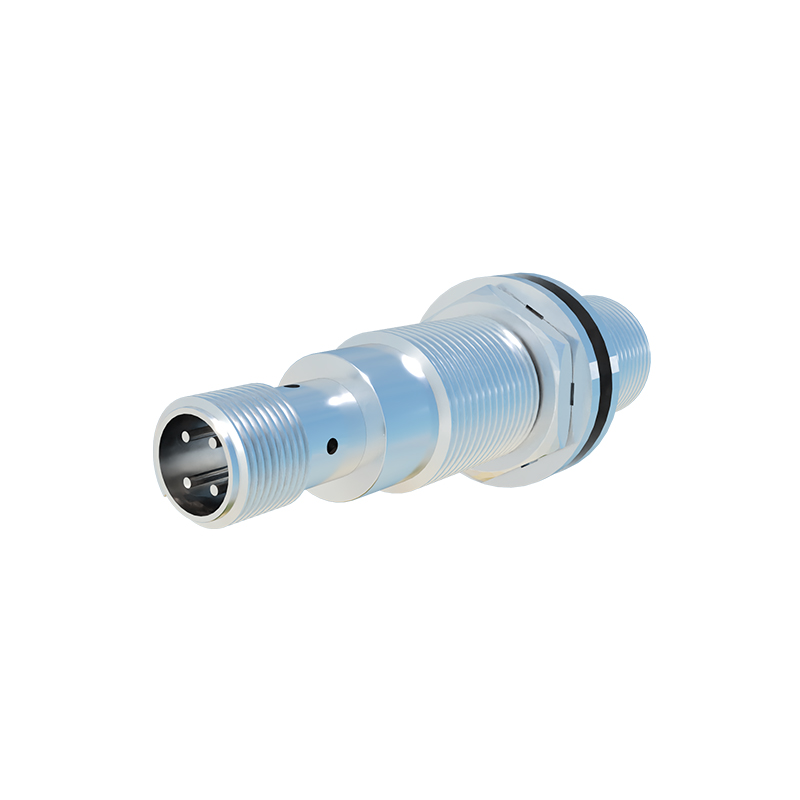
Internally, the sensor incorporates a voltage regulator or conditioning circuit. This component is vital. It steps down and stabilizes the incoming supply voltage (e.g., 24V DC) to the precise, lower DC levels (e.g., 5V or 3.3V) required by the sensitive integrated circuits and the oscillator. This regulation protects the core electronics from overvoltage and electrical noise, which are prevalent in industrial settings due to motors, solenoids, and welding equipment. High-quality sensors include filtering, surge protection, and reverse-polarity protection circuits to further shield the internal components.
The output configuration of the sensor is intrinsically linked to its power wiring and has major implications for circuit design. The two primary types are NPN (sinking) and PNP (sourcing) for DC sensors. In an NPN sensor, the output transistor connects the load to the negative common (0V). The load is permanently connected to the positive supply, and the sensor acts as a switch to ground. Conversely, a PNP sensor switches the positive supply to the load, which is connected to the common negative. Confusing these configurations is a common installation error that prevents operation. AC sensors typically use a relay or triac output, switching the AC load directly.
A critical, often overlooked, principle is the concept of "leakage current." Especially relevant for AC and some DC solid-state outputs, a small current (typically microamps to a few milliamps) can flow through the sensor's output even in its "OFF" state. This is due to the inherent design of semiconductor switching elements. If this leakage current is sufficient, it can inadvertently energize a highly sensitive load (like a PLC input module), causing a malfunction. Understanding the sensor's datasheet leakage specification and, if necessary, using a bleeder resistor in parallel with the load, is essential for reliable switching.
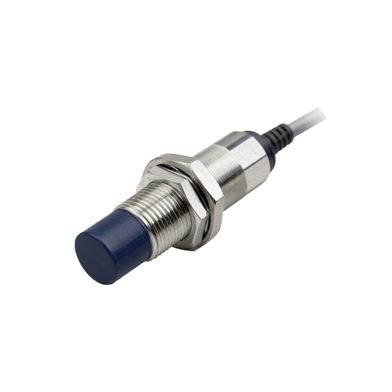
Design considerations for the power supply network are paramount. First, wire sizing must be adequate to prevent excessive voltage drop over long cable runs, ensuring the sensor receives voltage within its specified range. Second, decoupling or local filtering at the sensor's power terminals is recommended to suppress high-frequency noise. Third, in systems with many sensors, consider inrush current during simultaneous power-up, which may require a power supply with sufficient current headroom. Fourth, for sensors in safety-critical functions, using a dedicated, isolated, or monitored power supply can enhance reliability and diagnostic capability.
Furthermore, modern sensors with advanced features like IO-Link or analog outputs have more complex power needs. IO-Link sensors, while operating on a standard 24V DC line, use modulated communication on the same wires, requiring a compatible master module. Analog sensors demand an exceptionally clean and stable power supply, as any noise or ripple on the supply line can directly affect the accuracy of the output signal.
In conclusion, the power supply for a proximity sensor is a foundational engineering aspect far beyond simple connectivity. It involves understanding voltage ranges, internal regulation, output circuit topology, and real-world electrical phenomena like leakage current and noise. By meticulously applying these principles—selecting the correct voltage, configuring the NPN/PNP circuit properly, accounting for leakage, and designing a clean, robust power distribution network—engineers can guarantee that the sensing system forms a reliable and accurate backbone for any automated application. Always consult the manufacturer's datasheet for the specific electrical characteristics and requirements of the sensor in