Proximity sensors are critical components in modern industrial automation, enabling non-contact detection of objects with high precision and reliability. Proper installation is essential to ensure optimal performance, longevity, and safety. Among the key factors influencing installation, dimensional considerations stand out as fundamental. This guide delves into the intricacies of proximity sensor installation dimensions, covering industry standards, practical guidelines, and common pitfalls to avoid.
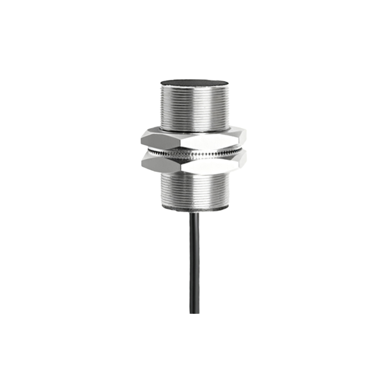
Understanding the core dimensional parameters begins with the sensor's body size and shape. Cylindrical sensors, widely used in manufacturing, are typically defined by their diameter (e.g., M8, M12, M18, M30) and length. The diameter directly affects the mounting hole requirements. For instance, an M12 sensor requires a 12mm diameter hole with appropriate tolerances, usually within ±0.1mm to prevent misalignment or physical stress. Threaded barrels simplify mounting but demand precise thread depth; insufficient engagement can lead to loosening under vibration, while excessive depth may damage internal components. Rectangular or block-style sensors, common in packaging and material handling, rely on pre-drilled mounting holes or slots, allowing for adjustable positioning. Their dimensions—height, width, and depth—must align with the mounting surface's space constraints and structural integrity.
Mounting distance and sensing range are interdependent dimensions that dictate sensor placement. The nominal sensing distance, specified by manufacturers (e.g., 2mm, 5mm, 10mm), indicates the maximum range for reliable detection under ideal conditions. However, installation must account for a safety margin, typically 10-20% less than the nominal value, to accommodate environmental variables like temperature fluctuations or target material variations. For inductive sensors detecting metals, the effective sensing distance can vary based on the target's material composition (e.g., steel vs. aluminum). Capacitive sensors, used for non-metallic objects, require even closer attention to mounting clearances to avoid interference from surrounding materials. Always refer to the sensor's datasheet for exact mounting distance recommendations, as improper spacing can cause false triggers or reduced sensitivity.

Orientation and alignment dimensions play a pivotal role in performance. Sensors should be mounted perpendicular to the target's approach direction to maximize detection consistency. Angular deviations beyond 5-10 degrees can significantly attenuate the sensing signal, especially for cylindrical models. For applications involving fast-moving objects, consider the target's size relative to the sensor's active surface; a small target may necessitate reduced mounting distances or specialized lens adjustments in photoelectric variants. Additionally, maintain adequate clearance between multiple sensors to prevent mutual interference—typically 1.5 to 2 times the sensor diameter for inductive types. In high-density installations, staggered mounting or shielding may be required to minimize crosstalk.
Environmental and mechanical dimensions cannot be overlooked. Proximity sensors often operate in harsh conditions involving dust, moisture, or mechanical vibrations. Ensure the mounting structure provides sufficient rigidity; flexible mounts can lead to dimensional drift over time, affecting calibration. For flush-mountable sensors, the mounting surface should be smooth and flat to prevent gaps that might allow contaminant ingress. Non-flush models require specific standoff distances from surrounding metal surfaces to avoid shielding effects—usually detailed in technical manuals as "side clearance" or "front clearance" dimensions. In washdown environments, verify IP (Ingress Protection) ratings and use appropriate sealing gaskets or locknuts to maintain dimensional integrity under thermal expansion or pressure changes.
Finally, documentation and standardization streamline installation processes. Adhere to international standards like IEC 60947-5-2 for dimensional tolerances and performance testing. Always cross-reference manufacturer drawings, which provide exact hole patterns, thread pitches, and torque specifications (e.g., 0.5-1.5 Nm for M12 threads). Use calibrated tools to achieve precise dimensions, and conduct post-installation tests with representative targets to validate detection consistency. Remember, even minor dimensional errors—such as a 0.5mm misalignment—can cascade into system failures, underscoring the need for meticulous planning and execution. By mastering these dimensional principles, engineers can enhance system reliability, reduce downtime, and extend sensor lifespan across diverse industrial applications.