In the realm of industrial automation and electrical control systems, proximity sensor switches are indispensable components. Their reliable, non-contact detection of metallic and non-metallic objects forms the backbone of countless processes, from assembly line sequencing to safety interlocks. However, the optimal performance and longevity of these sensors are heavily dependent on a suite of supporting accessories. This guide delves into the detailed diagram of proximity sensor switch accessories, elucidating the function and selection criteria for each component to ensure robust system integration.
A standard proximity sensor switch system diagram typically extends beyond the sensor itself. The core sensor, whether inductive, capacitive, or photoelectric, is just one node in a complete circuit. The primary accessories begin with the Mounting Hardware. This includes various brackets, flush-mount nuts, and sensing face protectors. Brackets allow for flexible orientation and secure fixation to machinery, mitigating vibration-induced failures. Flush-mount nuts enable the sensor to be installed level with a metal surface, protecting it from physical damage. For harsh environments, a Sensing Face Protector, often made of PTFE or stainless steel, shields the active surface from weld spatter, chips, and corrosive fluids, dramatically extending the sensor's operational life.
Wiring and connectivity form the next critical cluster in the diagram. Pre-wired Connectors and Connection Heads are paramount. Many sensors feature quick-disconnect M8 or M12 connectors, allowing for rapid replacement without rewiring. The choice between 3-wire (PNP/NPN) and 4-wire (NO+NC) configurations must align with the PLC input card specifications. Cable Glands and Flexible Conduits are essential for strain relief and environmental sealing, ensuring the cable entry point is protected against dust, moisture (IP67/IP69K ratings), and mechanical pull. For long cable runs or electrically noisy environments, Shielded Cables are mandatory to prevent electromagnetic interference (EMI) from causing false triggering.
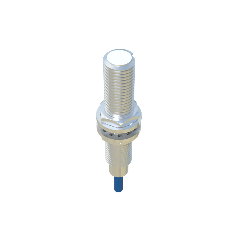
The electrical protection segment of the diagram is non-negotiable. Surge Protectors or Varistors are frequently installed in parallel with the sensor, especially in applications controlling inductive loads like solenoids or motors. They clamp voltage spikes and transients, preventing damage to the sensor's sensitive internal electronics. In DC circuits, Reverse Polarity Protection Diodes or modules safeguard the sensor from accidental incorrect power supply connections. For sensors with LED indicators, Series Resistors might be required if the indicator is driven directly from the supply voltage.
Furthermore, Functional Accessories enhance or modify sensor operation. Teach-in Modules or Remote Amplifiers allow for on-the-fly adjustment of sensing distance or output mode without physically accessing the sensor, which is invaluable in hard-to-reach locations. Timers and Logic Controllers can be integrated to add delay-on, delay-off, or one-shot pulse functions to the sensor's output signal, providing simple logic without programming a PLC.
Finally, no diagram is complete without considering Testing and Simulation Tools. A portable Sensor Tester simulates the presence of a target, allowing maintenance personnel to verify sensor operation and output status quickly. LED status indicators, while built-in, are considered a vital diagnostic accessory.
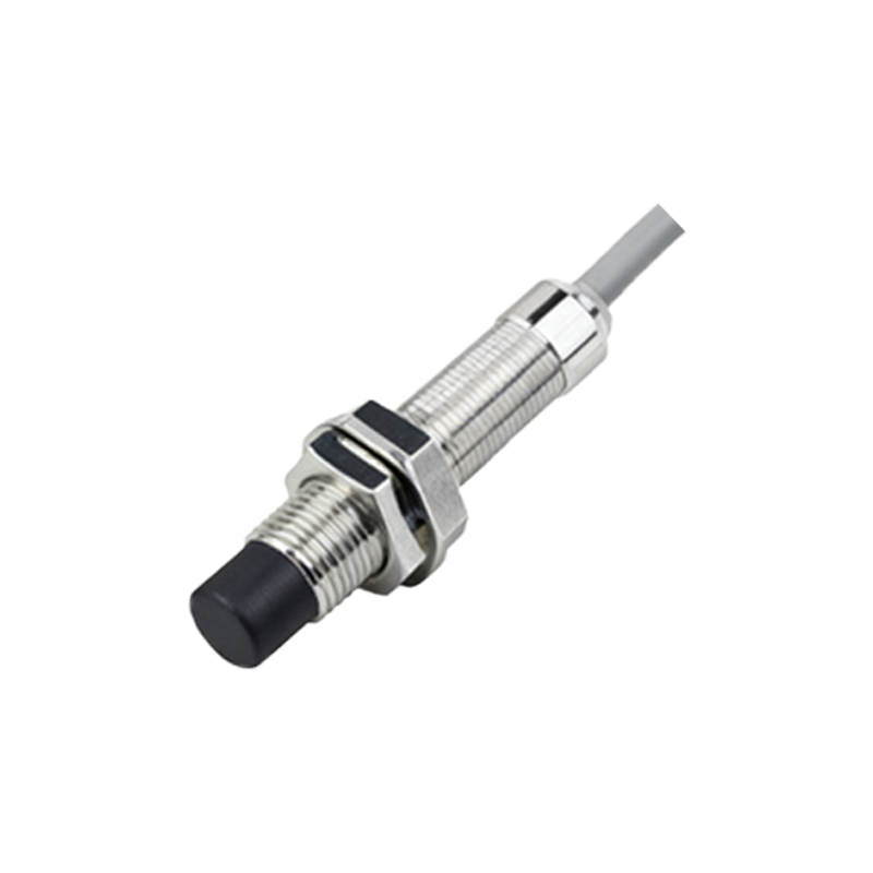
In conclusion, viewing a proximity sensor switch in isolation is a common oversight. The accompanying diagram of accessories—mounting hardware, wiring systems, protective devices, and functional add-ons—represents a holistic engineering approach. Proper selection and integration of these accessories, as detailed in the system diagram, are critical for achieving maximum reliability, safety, and performance in any automated electrical system. Always consult the sensor manufacturer's datasheet and accessory guides to ensure compatibility and optimal system design.