Infrared proximity sensors are widely used in industrial automation for non-contact detection, object positioning, and safety systems. Proper wiring is crucial to ensure reliable operation, minimize interference, and extend sensor lifespan. This guide outlines standard wiring practices for typical three-wire and four-wire DC infrared proximity sensors, common in factory environments.
Most industrial infrared proximity sensors operate on DC voltages, commonly 12-24V DC. They consist of an infrared LED emitter and a phototransistor or photodiode receiver. The wiring configuration typically includes power supply connections, output signal lines, and sometimes a separate control or diagnostic line.
For a standard three-wire DC sensor:
1. Brown wire: Connect to positive DC supply voltage (e.g., +24V).
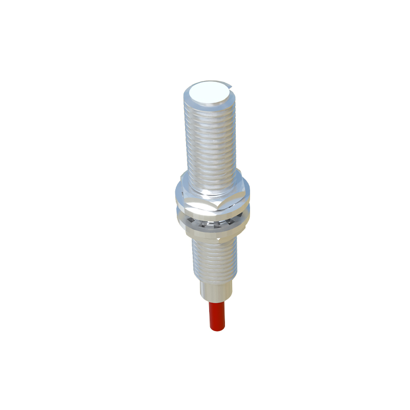
2. Blue wire: Connect to negative DC supply voltage (0V or ground).
3. Black wire: This is the output signal wire. In a normally-open (NO) configuration, it switches to supply voltage when an object is detected. It often connects to a PLC input, relay, or controller.
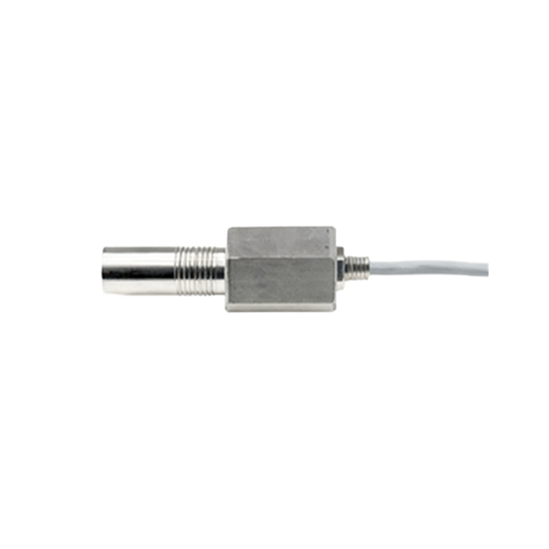
For a four-wire DC sensor, an additional wire (usually white or gray) provides a complementary output, such as a normally-closed (NC) signal or a second independent output channel. Always verify the manufacturer's datasheet, as wire colors can vary by brand and region.
Shielding and noise protection are critical in industrial settings. Use shielded cables, especially in environments with motors, variable frequency drives, or welding equipment. Ground the shield at the control panel end only to prevent ground loops. Maintain proper cable separation—keep sensor cables at least 10cm away from power cables to reduce electromagnetic interference.
For long cable runs exceeding 50 meters, consider voltage drop. Use thicker gauge wires (e.g., 18 AWG or larger) for power lines to maintain stable voltage at the sensor. Ensure all connections are secure using crimped terminals or soldering, and protect connections with conduit or cable glands in harsh environments.
Many infrared sensors feature diagnostic LEDs that indicate power status and detection state. Some advanced models include IO-Link or analog outputs for distance measurement, requiring additional wiring per communication standards. Always power down the circuit before wiring, and use a multimeter to confirm voltage polarity. Incorrect polarity can damage the sensor instantly.
Finally, perform functional testing after installation. Adjust the sensor's sensitivity potentiometer if available, and verify the detection range with target objects. Regular maintenance, including lens cleaning and connection checks, ensures long-term accuracy. By following these wiring guidelines, engineers can achieve robust and fail-safe infrared sensor integration in automated systems.