Proximity sensors are indispensable components in modern industrial automation, serving as the primary interface for non-contact object detection. The performance and reliability of these sensors are fundamentally governed by their main circuit design. This article delves into the core architecture, operational principles, and critical considerations for the main circuits of inductive, capacitive, and photoelectric proximity sensors, providing a comprehensive guide for engineers and technicians.
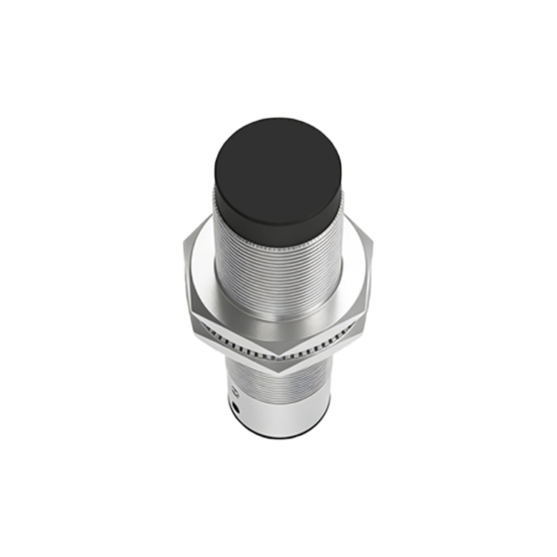
At the heart of an inductive proximity sensor lies an LC oscillator circuit. The main circuit typically consists of a high-frequency oscillator, a demodulator, a trigger, and an output switching stage. The oscillator generates an electromagnetic field via a coil and ferrite core assembly. When a metallic target enters this field, eddy currents are induced, causing a change in the oscillator's amplitude or frequency. This change is detected by the demodulator, which converts it into a DC signal. This signal then activates a trigger circuit (often a Schmitt trigger), which provides a clean, hysteresis-stabilized signal to drive the output stage. The output stage, usually comprising a transistor (PNP or NPN) in a sourcing or sinking configuration, switches the load connected to the sensor's supply voltage. Key design challenges include ensuring stable oscillation across temperature variations, providing sufficient sensing range, and achieving high noise immunity, especially in environments with strong electromagnetic interference (EMI). Shielding techniques and careful PCB layout are paramount.
Capacitive proximity sensors share a similar circuit topology but operate on a different principle. Their main circuit detects changes in capacitance formed between the sensor's active face and a target object. The circuit often employs an RC or relaxation oscillator where the sensing electrode forms part of the timing capacitor. The presence of any material (metal, plastic, liquid, etc.) with a dielectric constant different from air alters this capacitance, thereby changing the oscillator's frequency or charge/discharge time. This parameter shift is measured, typically by a frequency-to-voltage converter or a specialized IC, and processed to drive the output switch. A significant design aspect is the inclusion of compensation circuitry to nullify the effects of ambient humidity or contamination on the sensor face, which could cause false triggering. Sensitivity adjustment potentiometers are common to tailor the sensor for specific materials and applications, such as level detection of non-metallic substances.
Photoelectric sensors, particularly the modulated LED types, feature a more complex main circuit divided into transmitter and receiver sections. The transmitter circuit drives an infrared or visible-light LED with a high-frequency pulsed current (e.g., several kHz). This modulation is crucial for rejecting ambient light interference. The receiver circuit houses a phototransistor or photodiode. The faint signal from the receiver is first passed through a high-gain, low-noise amplifier, often with automatic gain control (AGC). It is then fed into a narrow-band filter or a synchronous demodulator tuned precisely to the transmitter's modulation frequency. This stage effectively extracts the weak useful signal from noise. The processed signal is compared against a threshold by a comparator to generate a clean digital output. Design focus areas include achieving long sensing distances, ensuring immunity to cross-talk from other sensors, and providing stable operation under varying ambient light conditions, from darkness to direct sunlight.
Common to all proximity sensor main circuits is the power supply section. Most industrial sensors operate on a wide DC range (10-30V DC) or standard AC voltages. Voltage regulation, reverse polarity protection, and transient voltage suppression (TVS diodes) are essential sub-circuits to ensure longevity and reliability in harsh electrical environments. Short-circuit and overload protection on the output is also a standard requirement.
Furthermore, modern "smart" sensors integrate microcontrollers into the main circuit. This allows for advanced features like programmable sensing modes, output delay timers, teach-in functionality for setting sensitivity, and digital communication interfaces (IO-Link). The microcontroller digitally processes the analog signal from the sensing element, enabling sophisticated diagnostics and parameterization.
In application, selecting the right sensor involves matching the main circuit's characteristics to the task. Inductive sensors are ideal for metals in machine automation. Capacitive sensors handle diverse materials in packaging or level control. Photoelectric sensors offer the longest range and are versatile for presence detection on assembly lines. Understanding the main circuit empowers engineers to troubleshoot effectively—whether it's diagnosing insufficient oscillator amplitude, compromised modulation in a photoelectric head, or EMI-induced glitches—and to specify sensors that will deliver robust, maintenance-free operation in demanding industrial settings.