In industrial automation and control systems, proximity sensors play a critical role in non-contact detection of metallic or non-metallic objects. Proper wiring and termination of these sensors to terminal blocks are fundamental to ensuring reliable operation, safety, and system longevity. This guide outlines best practices for connecting proximity sensors to terminal blocks, covering key considerations for electrical engineers and technicians.
Proximity sensors, including inductive, capacitive, and ultrasonic types, typically have three or four wires for power supply, output signal, and sometimes a diagnostic or complementary output. The common wire colors and functions are Brown (DC+ or L+), Blue (DC- or N), Black (Output or NO/NC), and White (Complementary Output or diagnostic line). It is paramount to consult the specific sensor's datasheet before wiring, as standards can vary by manufacturer and region.
The terminal block serves as the interface between the sensor cable and the control system's wiring, such as a PLC (Programmable Logic Controller) input module or a relay. Selecting the correct terminal block is the first step. Key selection criteria include: the voltage and current ratings matching or exceeding the sensor's requirements; the wire gauge compatibility for both the sensor cable and the field wiring; the terminal type (screw clamp, spring clamp, or push-in) suitable for the application environment (vibration, temperature); and compliance with relevant safety standards (e.g., UL, IEC).
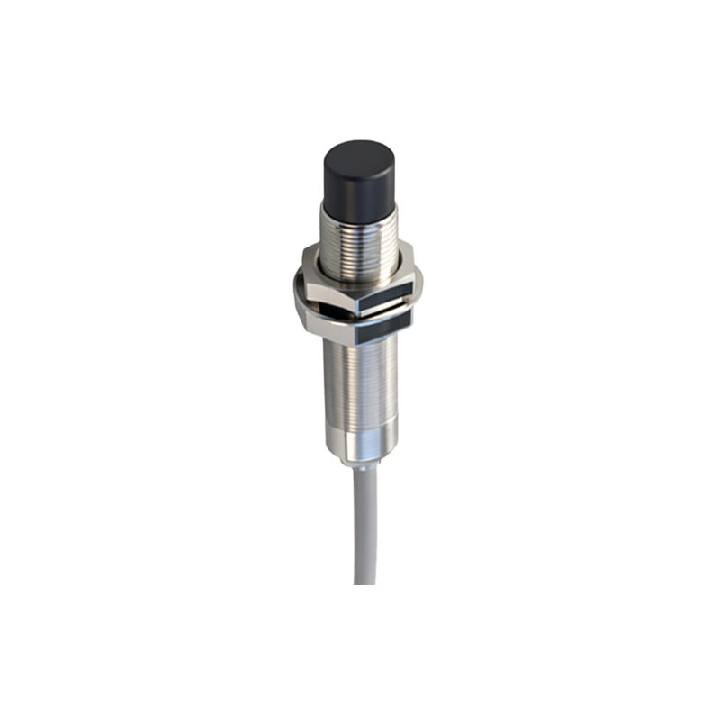
A standard wiring procedure for a 3-wire DC inductive proximity sensor to a terminal block involves several critical steps. First, ensure the power to the control circuit is completely isolated and locked out (LOTO procedure). Prepare the sensor cable by stripping the insulation to the length specified by the terminal block manufacturer, typically 7-10mm. Use ferrules on stranded wires to prevent fraying and ensure a secure, gas-tight connection, which is highly recommended in industrial settings to minimize contact resistance and potential failure points.
Identify the terminal block assignments. A typical terminal block for sensor connections will have markings for L+ (or +V), 0V (or COM), and Input (or IN). Connect the brown wire from the sensor to the L+ terminal. Connect the blue wire to the 0V or common terminal. Connect the black (output) wire to the designated input terminal. For a 4-wire sensor with a complementary output (e.g., white wire), connect it to a separate input terminal if both signals are required. Tighten the terminal screws to the manufacturer's specified torque using a calibrated torque screwdriver. Over-tightening can damage the wire or terminal, while under-tightening leads to high-resistance connections, heating, and eventual failure.
Shielding and grounding are vital for noise immunity, especially in environments with variable frequency drives (VFDs), motors, or welding equipment. Most proximity sensor cables include a braided or foil shield. This shield should be connected to the functional earth (FE) or shield ground terminal at the terminal block end only. The shield must not be connected at the sensor housing end to avoid ground loops. Use a terminal block with a dedicated shield clamping section or a separate grounding terminal. The drain wire (if present) from the shield should be secured under this clamp.
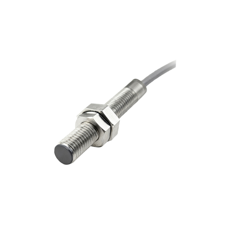
After wiring, perform thorough verification. Visually inspect for proper seating of wires, absence of stray strands, and secure cable strain relief. Use a multimeter to check for continuity between the sensor pins and the corresponding terminal block points. Power the circuit and test the sensor's operation by introducing a target material at its sensing distance. Monitor the output signal at the terminal block with a multimeter or the PLC's diagnostic software to confirm correct switching.
Common pitfalls to avoid include mixing up NPN (sinking) and PNP (sourcing) sensor outputs relative to the PLC input type, which will prevent signal detection. Incorrect power supply polarity can damage the sensor. Neglecting to use the shield or grounding it at both ends introduces electrical noise. Using terminal blocks not rated for the environmental conditions (e.g., high humidity, corrosive atmosphere) leads to premature corrosion and failure.
In conclusion, meticulous attention to terminal block selection, proper wiring techniques, correct shielding practices, and systematic verification are the cornerstones of a robust proximity sensor installation. Adhering to these industry-standard practices minimizes downtime, enhances safety, and ensures the precision required in modern automated systems. Always prioritize the manufacturer's instructions and applicable electrical codes for your specific installation.