Proximity sensors are fundamental components in modern automation, robotics, and safety systems. They detect the presence or absence of an object without physical contact, using various physical principles. For engineers and hobbyists, understanding how to construct a basic proximity sensor is an excellent exercise in applied electronics and sensing technology. This guide will walk you through creating a simple yet effective inductive proximity sensor, commonly used for detecting metallic objects.
Understanding the Core Principle
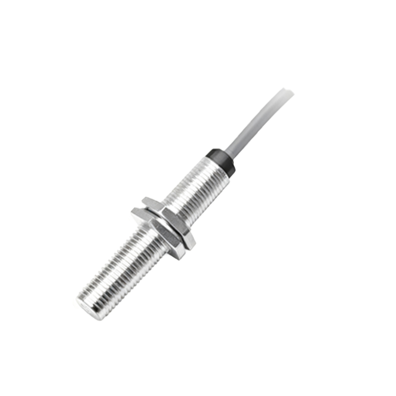
Inductive proximity sensors operate on the principle of electromagnetic induction. The core component is a coil. When an alternating current passes through this coil, it generates an oscillating electromagnetic field around it. When a metallic object enters this field, eddy currents are induced on the object's surface. These eddy currents draw energy from the coil, which in turn changes the coil's inductance and the amplitude of the oscillation. This change can be detected and converted into a usable output signal (e.g., a digital high/low).
Required Components and Tools
To build a basic inductive proximity sensor, you will need the following:
Oscillator Circuit Components: A coil (inductor), a capacitor (to form an LC tank circuit), and an oscillator IC (like a 555 timer or a dedicated oscillator).
Detection Circuit: A diode for rectification, a capacitor for filtering, and a comparator IC (like an LM393).
Output Stage: A transistor (e.g., NPN like 2N2222) or an optocoupler for switching, and a relay or an LED for indication.
Power Supply: A stable DC power source (e.g., 5V or 12V).
Core Material: A ferrite core to shape and concentrate the electromagnetic field of the coil.
Housing: A cylindrical housing (often metal-threaded barrel) for physical protection and mounting.
Essential Tools: Soldering iron, multimeter, oscilloscope (helpful for debugging), and basic hand tools.
Step-by-Step Construction Process
1. Design the Oscillator Tank Circuit:
The first stage is to create a stable high-frequency oscillator. Wind your coil around the ferrite core; the number of turns will affect sensitivity and range. Connect this coil in parallel with a capacitor to form the LC tank circuit. This circuit determines the resonant frequency, typically in the range of 100 kHz to 1 MHz. Use an oscillator circuit (a 555 timer in astable mode or a transistor-based Colpitts oscillator) to drive this tank. The oscillator should produce a clean sine or square wave at the resonant frequency.
2. Build the Detection and Demodulation Circuit:
The output from the oscillator coil is AC. We need to convert the change in amplitude caused by a target into a DC voltage. Connect a diode and a filter capacitor to the coil's output to create a simple envelope detector or peak detector. This circuit rectifies the AC signal and outputs a DC voltage proportional to the oscillation's amplitude. When no metal is present, this DC voltage is at its highest. When a metal object approaches, the amplitude drops, causing this DC voltage to decrease.
3. Integrate the Comparator:
Feed the DC voltage from the detector into the non-inverting input of a comparator IC (e.g., LM393). Set a reference voltage using a voltage divider on the comparator's inverting input. This reference voltage defines the sensing threshold. Adjust it using a potentiometer for calibration. When the detected DC voltage falls below the reference voltage (meaning an object is detected), the comparator's output switches state (e.g., from high to low).
4. Implement the Output Stage:
The comparator's output is typically low-current. To drive a load like an LED, relay, or PLC input, use a transistor switch. Connect the comparator output to the base of an NPN transistor through a current-limiting resistor. The load (e.g., an LED in series with a resistor) is placed between the collector and the positive supply. When the comparator goes low, it turns off the transistor, which can be configured to turn on the load. Alternatively, an optocoupler provides excellent electrical isolation for industrial interfaces.
5. Assembly, Shielding, and Calibration:
Place the coil and ferrite core at the front of the metal housing. Pot the entire electronics assembly behind it with epoxy resin for vibration resistance and environmental protection. The metal housing itself acts as an electrostatic shield, preventing the field from extending radially and making the sensor directional. Connect power and output wires. Use a multimeter to monitor the detector's DC voltage while bringing a standard metal target (usually mild steel) towards the sensor face. Adjust the threshold potentiometer until the output switches at