In the realm of industrial automation and machinery, precise detection of objects without physical contact is a fundamental requirement. Among the diverse array of non-contact sensing solutions, the groove type proximity sensor stands out for its unique design and reliable performance in specific applications. This article delves into the operational principles, key features, common applications, and critical selection criteria for these specialized sensors.
At its core, a groove type proximity sensor, also known as a slot or through-beam sensor, consists of a U-shaped housing that creates a physical "groove" or slot. Within this housing, an emitter (typically an infrared LED) and a receiver (such as a phototransistor) are positioned on opposite sides of the groove. The fundamental working principle is based on the modulation of a light beam. The emitter continuously projects a beam of light across the gap to the receiver. When an object passes through this groove, it interrupts the light beam. The receiver detects this interruption and triggers a change in the sensor's output state, signaling the presence of the object. This through-beam configuration offers high accuracy and is generally less susceptible to environmental factors like color or surface finish of the target object compared to some diffuse reflection sensors.
The defining characteristic of these sensors is their physical structure. The groove provides a defined sensing window, ensuring that detection occurs only when an object physically passes through this specific aperture. This makes them exceptionally useful for counting, positioning, or verifying the presence of objects with consistent profiles, such as tabs on a rotating shaft, PCB boards on a conveyor, or labels on a packaging line. They excel in applications requiring edge detection or verifying if an object has a specific protruding feature.
Several technical specifications are paramount when evaluating groove type proximity sensors. First is the slot width and depth, which determine the maximum size of the object that can be detected and the required mounting clearance. The sensing object, often specified as a minimum opaque object size (e.g., 1.0mm x 1.0mm), is crucial for reliable operation. Response time, usually in microseconds, defines how quickly the sensor can detect an object passing at high speed. Output types are another key consideration; common outputs include DC NPN/PNN transistors (sinking or sourcing), which interface with PLCs, or solid-state relay outputs. Many modern sensors also feature built-in amplifiers with adjustable sensitivity or hysteresis to fine-tune performance against ambient light or vibration.
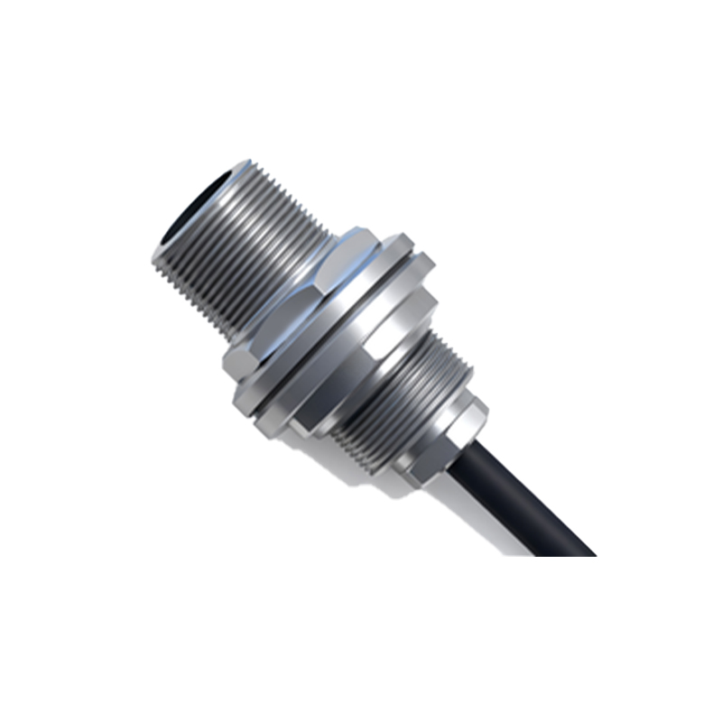
The application spectrum for groove sensors is broad within automated systems. They are extensively used in:
- Rotary Encoder Systems: Detecting slots or teeth on an encoder disk to measure speed or position.
- Conveyor Line Counting & Verification: Ensuring products are present and correctly oriented before packaging or processing.
- Printing and Labeling Machinery: Detecting the leading edge of paper, labels, or cartons for precise registration.
- Security and Access Control: Acting as a safety interlock by detecting when a door or guard is properly closed.
- Small Parts Assembly: Verifying the presence of components like screws, springs, or pins.
Selecting the right groove sensor requires a careful analysis of the operating environment and application needs. Key factors include:
1. Object Characteristics: Size, material (must be opaque to the sensor's light wavelength), and speed of passage.
2. Environmental Conditions: Exposure to dust, oil, coolant, or intense ambient light may necessitate sensors with higher IP (Ingress Protection) ratings, such as IP67, and robust housing materials like nickel-plated brass or stainless steel.
3. Electrical Requirements: Operating voltage range (commonly 10-30V DC) and output configuration must match the control system's input card.
4. Mounting Constraints: The sensor's physical dimensions and required mounting brackets must fit the available space.
5. Special Features: Some applications may require sensors with a "light-ON" or "dark-ON" logic selectable function, or a built-in timer function for delaying the output signal.
In conclusion, groove type proximity sensors offer a simple, yet highly effective solution for through-beam optical sensing within a confined, protected space. Their design provides inherent alignment accuracy and protection for the optical components. By understanding their operating principle, key specifications, and application fit, engineers and technicians can effectively integrate these sensors to enhance the reliability, safety, and efficiency of automated equipment. As with all sensing components, consulting the manufacturer's datasheet and, when possible, testing the sensor in the actual application environment is the best practice for ensuring optimal performance and longevity.