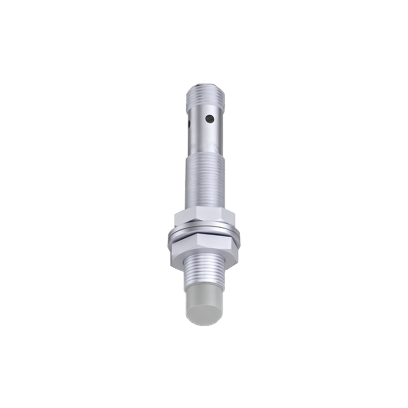
In industrial automation and control systems, proximity sensors play a crucial role in detecting the presence or absence of objects without physical contact. Among various wiring configurations, the two-wire connection method stands out for its simplicity, cost-effectiveness, and reliability. This article delves into the technical aspects, installation guidelines, and practical considerations for implementing two-wire proximity sensors in electrical engineering projects.
Two-wire proximity sensors integrate the sensor element and switching device into a single unit, requiring only two wires for both power supply and signal transmission. Unlike three-wire or four-wire sensors, which have separate power and output lines, two-wire sensors simplify wiring layouts and reduce installation time. They are commonly used in applications where space is limited or where minimizing wiring complexity is a priority, such as in conveyor systems, machine tools, and packaging machinery.
The operating principle of a two-wire proximity sensor is based on the modulation of current flow. In the absence of a target, the sensor draws a small leakage current (typically a few milliamperes) to maintain standby operation. When a target enters the sensing range, the internal switching mechanism activates, allowing a higher current to flow (usually up to 200 mA, depending on the model), which is detected by the connected controller like a PLC or relay. This current change serves as the output signal, indicating the target's presence.
Wiring a two-wire proximity sensor involves connecting one wire to the positive DC supply voltage (commonly 10-30 VDC) and the other to the load, which is then linked to the negative supply terminal. It is essential to observe polarity, as incorrect connections can damage the sensor or cause malfunction. Additionally, a protective element such as a fuse or circuit breaker should be included in the circuit to prevent overcurrent conditions. For AC-powered sensors, similar principles apply, but attention must be paid to voltage ratings and frequency compatibility.
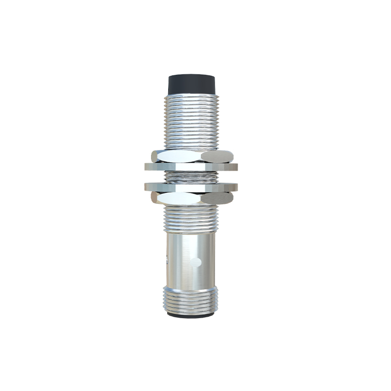
Key advantages of the two-wire method include reduced wiring costs, lower maintenance requirements, and enhanced durability due to fewer connection points. However, engineers must consider limitations like voltage drop across the sensor, which can affect performance in long cable runs, and the need for a minimum load current to ensure proper switching. Selecting the right sensor involves evaluating factors such as sensing distance, output type (normally open or normally closed), environmental conditions (e.g., temperature, humidity), and material compatibility (e.g., for detecting metal or non-metal objects).
In practice, installation should follow manufacturer specifications, including proper mounting alignment, avoidance of mutual interference between multiple sensors, and shielding from electromagnetic noise. Regular testing with a multimeter or oscilloscope can verify signal integrity and troubleshoot issues like false triggers or sensor drift. For optimal performance, integrate two-wire sensors with compatible controllers and ensure power supply stability within the rated range.
As technology advances, modern two-wire proximity sensors offer features like short-circuit protection, reverse polarity protection, and LED indicators for status monitoring. These enhancements improve system reliability and safety in demanding industrial environments. By mastering the two-wire connection method, electrical engineers can design efficient, robust automation systems that meet operational goals while adhering to industry standards such as IEC 60947-5-2.

In summary, the two-wire proximity sensor provides a streamlined solution for object detection in various industrial settings. Its straightforward wiring, combined with careful selection and installation, ensures long-term functionality and cost savings. Whether upgrading existing machinery or implementing new automation lines, understanding this method is essential for professionals in the electrical engineering field.