In industrial automation systems, proximity sensors play a critical role in detecting the presence or absence of objects without physical contact. Their ability to initiate or halt machine operations—commonly referred to as start-stop control—is fundamental to ensuring efficiency, safety, and precision. This article delves into the wiring methodologies for implementing start-stop control using proximity sensors, focusing on practical configurations, safety considerations, and industry-standard practices.
Proximity sensors, including inductive, capacitive, and photoelectric types, generate output signals when a target object enters their sensing range. For start-stop applications, these sensors are typically integrated into control circuits to trigger actions such as motor activation, conveyor belt movement, or robotic arm cycles. The wiring approach depends on the sensor output type (e.g., NPN, PNP, or relay) and the control system design (e.g., relay-based or PLC-based).
In a basic relay-based start-stop circuit, a proximity sensor is wired in series with a control relay. When the sensor detects an object, its output closes or opens a contact, energizing the relay coil. This, in turn, actuates the relay’s contacts to start or stop a load, such as a motor starter. For instance, in an NPN (sinking) sensor configuration, the output wire connects to the relay coil’s negative terminal, while the positive terminal is linked to the power supply. Upon detection, the NPN sensor sinks current to ground, completing the circuit and energizing the relay. Conversely, a PNP (sourcing) sensor provides positive voltage to the relay coil, with the other side connected to ground. It is crucial to match the sensor polarity with the control system to avoid malfunctions or damage.
For enhanced safety in start-stop control, dual-channel wiring with redundancy is often employed. This involves using two proximity sensors or a single sensor with dual outputs wired to safety relays. If one channel fails, the safety relay prevents unintended machine starts, adhering to standards like ISO 13849. Additionally, emergency stop (E-stop) circuits should be integrated separately, using normally closed (NC) contacts to ensure fail-safe operation. The proximity sensor’s output can be wired in parallel or series with E-stop buttons, depending on the logic—typically, a stop command overrides the start signal.
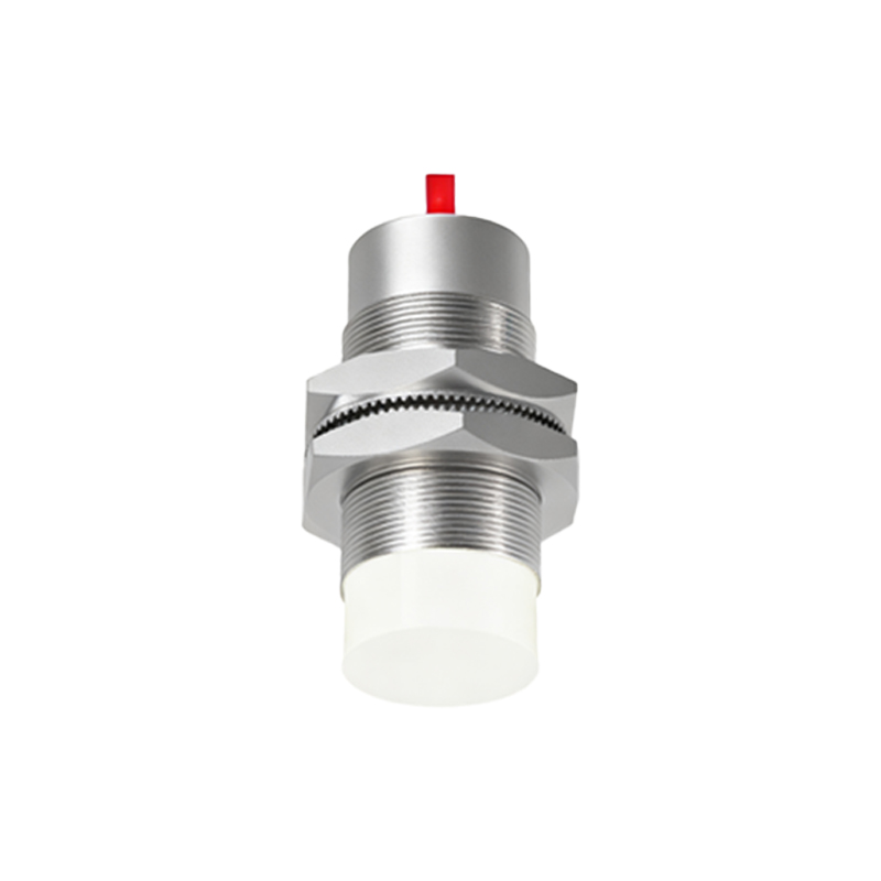
In PLC-based systems, wiring proximity sensors for start-stop control involves connecting the sensor outputs to digital input modules. The sensor’s signal (e.g., 24V DC for PNP) is fed into the PLC input, which then executes programmed logic to control outputs like contactors or motor drives. Shielding and proper grounding are essential to mitigate electrical noise, especially in environments with motors or variable frequency drives. Twisted pair cables and separate conduits for power and signal lines help maintain signal integrity.
When designing start-stop circuits, consider the sensor’s load capacity and switching frequency. Proximity sensors with solid-state outputs (NPN/PNP) are suitable for high-speed applications but may require interposing relays for heavy loads. Relay-output sensors can handle higher currents directly but have slower response times. Always refer to manufacturer datasheets for voltage, current, and temperature ratings. For example, a typical inductive sensor might support up to 200mA load current, sufficient to drive a small relay coil but inadequate for a motor starter—hence, an intermediate relay is necessary.
Maintenance and troubleshooting are simplified by using indicator lights on sensors and control panels. Wiring diagrams should clearly label terminals (e.g., brown for +V, blue for 0V, black for output) and include test points for voltage checks. Common issues include miswiring, sensor misalignment, or supply voltage fluctuations, which can be diagnosed with a multimeter. Regular inspections ensure reliable operation, preventing downtime in automated processes.
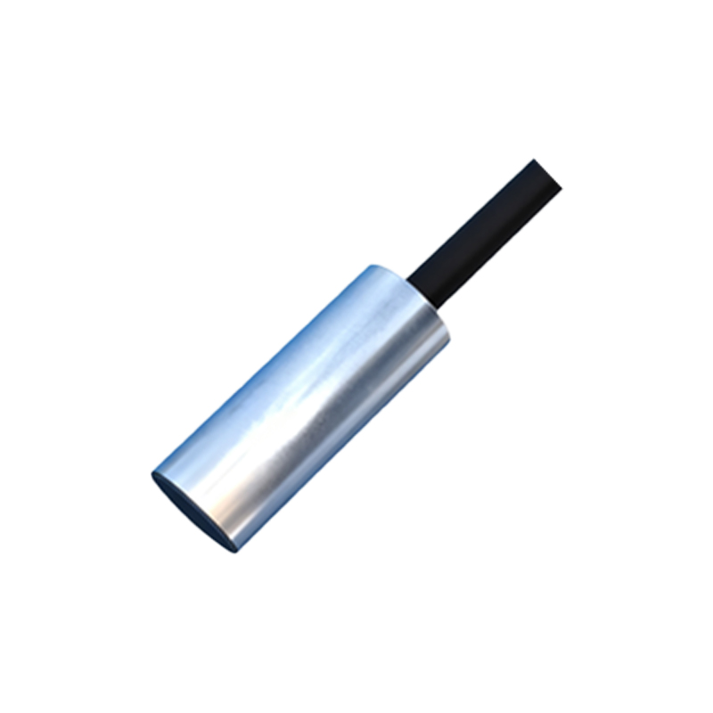
In summary, proximity sensor wiring for start-stop control requires attention to output types, safety protocols, and environmental factors. By following industry standards and leveraging appropriate circuit designs, engineers can build robust automation systems that enhance productivity while prioritizing operator safety. As technology evolves, smart sensors with IO-Link or Ethernet connectivity offer advanced diagnostics, but the core wiring principles remain rooted in electrical fundamentals.