In industrial automation and machinery safety systems, proximity sensors play a critical role in detecting the presence or absence of objects without physical contact. Proper installation and connection are paramount to ensure reliable operation, longevity, and compliance with safety standards. This guide outlines the fundamental steps and considerations for connecting a proximity sensor correctly.
First, identify the sensor type. Proximity sensors are broadly categorized by their sensing technology: inductive (for metallic objects), capacitive (for both metallic and non-metallic materials), and ultrasonic (for distance measurement). Each type has specific wiring requirements. Check the manufacturer's datasheet for the model's specifications, including operating voltage (commonly 10-30V DC or 90-250V AC), output type (PNP/NPN for DC, or relay/SSR for AC), and current rating.
Before starting any electrical work, ensure the power supply is completely disconnected and locked out to prevent accidental energization. Verify the sensor's housing integrity and environmental rating (e.g., IP67 for dust and water resistance) to confirm suitability for the installation location.
Wiring a DC proximity sensor typically involves three or four wires. For a three-wire DC sensor:
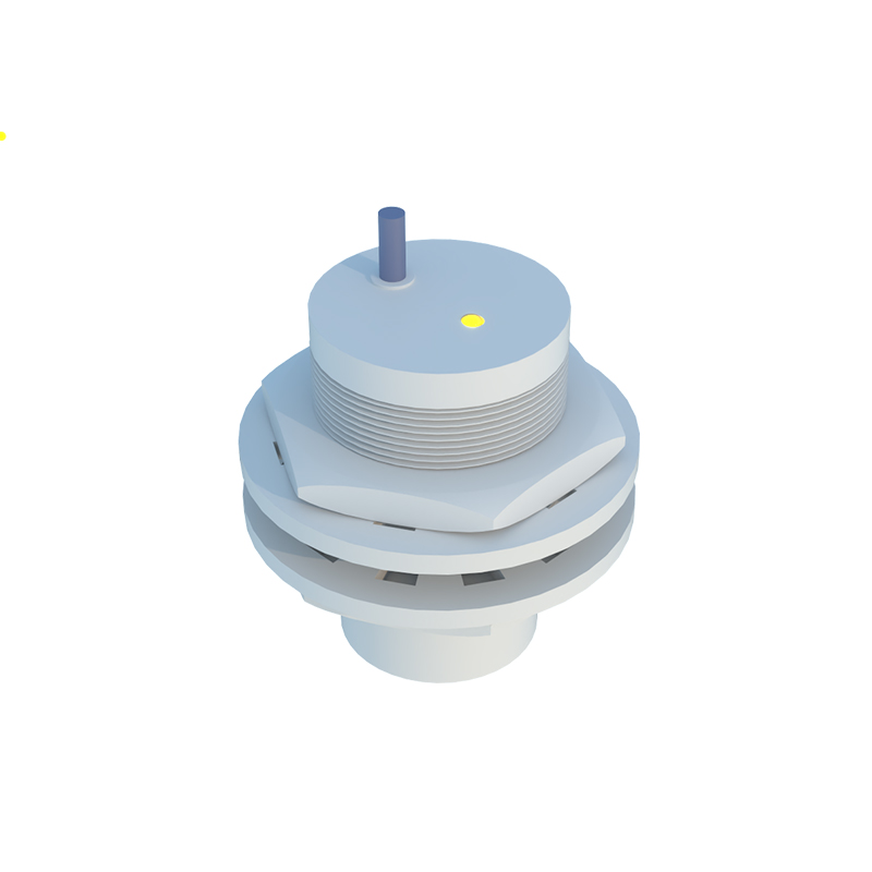
- Brown wire: Connect to the positive supply voltage (+V).
- Blue wire: Connect to the common negative or ground (0V).
- Black wire: This is the output signal wire. For a PNP (sourcing) sensor, it provides a positive voltage when activated and connects to the load (e.g., PLC input). For an NPN (sinking) sensor, it switches the ground path and connects to the load's negative side.
Some sensors include a white wire for complementary output or diagnostic functions—refer to the manual. Use shielded cables in electrically noisy environments, grounding the shield at one end to the control panel's earth ground to minimize interference.
For AC-powered sensors, wiring usually involves two or three wires:
- Brown wire: Live/hot wire (L).
- Blue wire: Neutral wire (N).
- Black wire: Output load wire.
Ensure proper grounding via the designated terminal or housing connection. AC sensors often have built-in surge protection, but additional external protection may be needed in areas with voltage spikes.
After wiring, perform a systematic check:
1. Visually inspect connections for tightness and correct polarity.
2. Use a multimeter to verify voltage levels before and after activation.
3. Test the sensor by introducing a target object within its sensing range. Observe the output indicator LED (if present) and monitor the connected device (e.g., PLC status light) for correct response.
4. Adjust the sensor's sensitivity or sensing distance if applicable, ensuring it does not trigger falsely due to background interference.
Common pitfalls to avoid include mixing PNP and NPN wiring with incompatible PLC inputs, exceeding cable length limits (which can cause voltage drop or signal degradation), and ignoring environmental factors like temperature extremes, chemical exposure, or mechanical vibration. Always follow the sensor's mounting guidelines—maintain the recommended clearance around the sensing face to prevent side-effects from adjacent metal.
In safety-critical applications, such as machine guarding, use redundant sensors or certified safety-rated devices (e.g., Type 4 PL e according to ISO 13849) and integrate them into a safety relay circuit. Regularly schedule maintenance checks to clean the sensing surface and verify electrical connections, as corrosion or loose terminals can lead to failures.
Proper connection not only ensures operational efficiency but also enhances workplace safety by preventing malfunctions that could lead to equipment damage or personal injury. Always prioritize manufacturer instructions and relevant electrical codes, such as NEC, IEC, or local regulations, during installation.