Laser distance sensors are critical components in industrial automation, robotics, and quality control systems. Their ability to provide precise, non-contact measurements makes them indispensable. However, achieving reliable and accurate readings requires proper calibration and systematic debugging. This guide outlines practical steps for technicians and engineers to optimize sensor performance.
The initial phase involves pre-deployment verification. Before installation, inspect the sensor for physical damage, especially the lens and housing. Verify the electrical specifications—supply voltage, output type (analog, digital, pulse), and current draw—match your system's requirements. Incorrect power supply is a common source of failure. Consult the manufacturer's datasheet for the exact operating parameters.
Environmental setup is paramount. Laser sensors are sensitive to ambient conditions. Ensure the operating temperature and humidity are within the specified range. Strong ambient light, particularly from other lasers or direct sunlight, can interfere with the sensor's receiver. Install protective shrouds or filters if necessary. The target surface characteristics significantly affect readings. For highly reflective, dark, or transparent surfaces, you may need to adjust the sensor's sensitivity or use a calibration target with known reflectance properties provided by the manufacturer.
Mounting and alignment constitute the most frequent source of error. The sensor must be securely fixed to minimize vibration. The laser beam must be perpendicular to the target surface. Even a slight angular deviation can introduce a cosine error, resulting in a measured distance longer than the true perpendicular distance. Use precision mounting fixtures and a digital inclinometer for alignment. For measuring moving objects, ensure the beam is focused on the intended measurement point throughout the object's travel path.

Calibration is not a one-time event but a process. Begin with a reference calibration using gauge blocks or a fixed target at a known distance. Most sensors have a teach-in function or calibration mode. Follow this procedure: place the target at the minimum measurement distance, trigger the "set min" command, then move it to the maximum distance and trigger "set max." This establishes the scaling for the output signal. For analog output sensors, use a multimeter or data acquisition system to verify that the output voltage or current corresponds correctly to the distance range. Document the input values and the corresponding output readings.
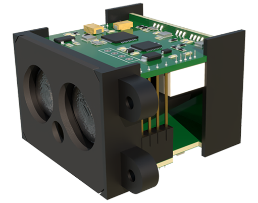
Debugging is a logical, step-by-step investigation. If the sensor provides unstable readings or fails to detect a target, follow this sequence:
1. Check Power and Connections: Confirm stable power and intact wiring. Loose connectors are a typical culprit.
2. Observe the Indicator LEDs: Most sensors have status LEDs. A solid power LED and a blinking measurement LED indicate normal operation. Refer to the manual for diagnostic blink codes.
3. Verify the Measurement Window: Ensure no obstructions are blocking the beam path. Even dust or condensation on the lens can cause errors.
4. Assess the Target: Test with a standard, high-reflectivity target (like white paper). If readings stabilize, the original target material is the issue.
5. Review Configuration Settings: Access the sensor's parameters via buttons or software. Check the response time, switching threshold, and output logic. A response time set faster than the object's speed can cause missed detections.
6. Monitor the Output Signal: Use an oscilloscope to examine the signal quality for noise. Electrical noise from motors or drives can be mitigated by using shielded cables, separating sensor wiring from power lines, and ensuring proper grounding.
7. Firmware and Software: Ensure the sensor's firmware and any accompanying PC configuration software are up to date.
Advanced troubleshooting may involve temperature compensation. If measurements drift over time as the environment heats up, the sensor may require compensation. Some high-end models have built-in temperature sensors and automatic compensation. For others, you may need to establish a temperature-correction curve based on empirical data.
Finally, implement a routine maintenance schedule. Periodically clean the lens with appropriate materials, re-check calibration against a master gauge, and log performance data to identify gradual degradation. By adhering to a rigorous calibration protocol and a structured debugging methodology, you can ensure your laser distance sensors deliver the precision and reliability required for critical applications, minimizing downtime and maintaining system integrity.