In industrial automation and control systems, proximity switches utilizing Hall effect sensors represent a critical category of non-contact detection components. A high-quality photograph of such a sensor is not merely an image; it is a detailed visual document that reveals design, construction, and potential application suitability. This article provides a technical analysis of key features observable in a standard proximity switch Hall sensor photo, aimed at engineers and procurement specialists.
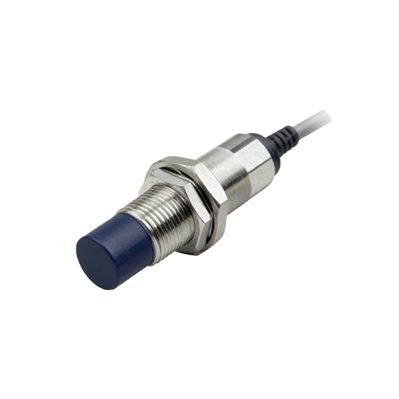
Examining the external housing is the first step. A typical photo will show a robust, often cylindrical or rectangular, metal or polymer casing. The material, visible through texture and labeling, indicates environmental resilience. A stainless-steel housing, for instance, suggests IP67 or higher ingress protection, suitable for washdown or outdoor environments. The color, frequently nickel-plated or black, can also hint at material grade and corrosion resistance. The form factor—barrel-style, limit-switch style, or ring-shaped—is immediately apparent and dictates mounting methodology.
The sensing face is the most crucial area. In a Hall-based proximity switch, this is where the integrated circuit containing the Hall element is located behind a thin wall. A clear photo should show this face as a smooth, flat surface, often marked with a symbol indicating the sensing type (e.g., a magnetic field icon) or the effective sensing distance. The proximity to which a permanent magnet or a ferromagnetic target (like a gear tooth) will trigger the switch depends on the internal design, but the physical size of the face correlates generally with the sensing range and magnetic field sensitivity.
Electrical connection points are prominently featured. Most industrial proximity switches exhibit either a pre-attached cable (with strain relief visible at the housing entry) or a connector interface, such as a quick-disconnect M8 or M12 connector. The number of pins (3-pin or 4-pin) is clearly countable in a good photo. A 3-pin device typically provides NPN or PNP transistor output, while a 4-pin often offers both a normally open and a normally closed signal, or a dual-channel differential output for precise position sensing. The cable color coding—brown (V+), blue (V-), black (output), and sometimes white (complementary output)—should be distinct if present.
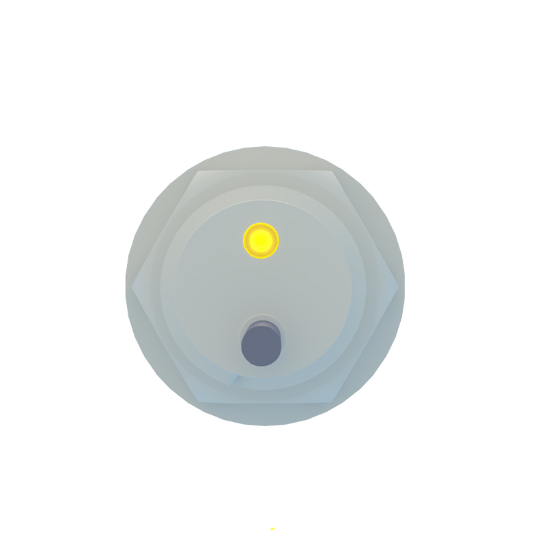
Status indicators are a small but vital visual clue. Many modern Hall proximity switches incorporate an LED, usually embedded near the connection end. In a photo, this LED, if present, is a clear dot. Its color (red, green, or yellow) indicates the operational state—power on or output activation. This feature is invaluable for on-site diagnostics and commissioning, allowing technicians to verify sensor operation without external equipment.
Labeling and engraving on the housing provide the definitive technical data. A sharp photo will reveal the manufacturer's logo, part number, and essential electrical specifications. Key parameters include the operating voltage range (e.g., 10-30V DC), output type (NPN/PNP, NO/NC), and the rated current. Compliance markings like CE, UL, or the ATEX flameproof symbol for hazardous areas are also critical identifiers for application in regulated industries. The sensing distance, often denoted as "Sn," is a paramount specification etched on the body.
Beyond the unit itself, context in a photo can be informative. Some product photos show the sensor installed—for example, mounted on a bracket near a gear to detect rotation or positioned along a linear actuator track. This demonstrates recommended mounting clearances, the orientation relative to the target, and typical industrial environments. Other photos might include a target, such as a small magnet or a metal flag, to illustrate the activation principle.
For an engineer, analyzing such a photo aids in selection, integration, and troubleshooting. The physical size confirms fit in a cramped control panel. The connector type dictates the required mating cable harness. The housing material ensures longevity in the intended environment. A clear visual of the sensing face helps in determining the optimal alignment with the moving target to ensure reliable switching without physical contact.
In conclusion, a detailed photograph of a proximity switch Hall sensor serves as a primary technical reference. It bridges the gap between datasheet specifications and physical implementation. By systematically evaluating the housing, sensing face, electrical connections, indicators, and markings visible in the image, professionals can make informed decisions to ensure robust and reliable performance in automated machinery, safety systems, and precision measurement applications. Always cross-reference the visual data with the official manufacturer's datasheet for complete electrical and environmental ratings.