In industrial automation and control systems, proximity sensors are indispensable components for non-contact detection of metallic or non-metallic objects. Their reliability, however, is intrinsically linked to correct and secure mounting. Improper installation can lead to false triggers, reduced sensing range, physical damage, and ultimately, costly downtime. This article outlines critical best practices for mounting inductive, capacitive, and magnetic proximity sensors to ensure optimal performance and longevity.
The foundation of successful mounting begins long before physical installation: understanding the sensor's specifications and the application environment. Key parameters include the sensor's nominal sensing distance (Sn), its housing material and style (e.g., cylindrical, rectangular, threaded, or non-threaded), and its ingress protection (IP) rating. The operating environment must be assessed for factors such as temperature extremes, potential chemical exposure, vibration levels, and the presence of electrical noise or other nearby sensors.
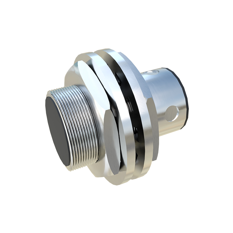
For cylindrical, threaded inductive proximity sensors, which are among the most common, mounting requires precise attention. The sensor should be mounted using the correct size locknut, typically provided by the manufacturer. It is crucial to avoid overtightening, which can distort the housing, damage the sensing face, or strip threads. A common guideline is to tighten the locknut finger-tight and then use a wrench for a final quarter to half turn. The sensor must be positioned so that the target approaches the active sensing face perpendicularly. For optimal and repeatable detection, the target should be a standard material (like mild steel for inductive sensors) and have a surface area at least equal to the diameter of the sensor's sensing face. Maintaining a mounting distance from surrounding metal is also vital. Most datasheets specify a "non-flush" or "flush-mountable" designation. Non-flush sensors require a clear, metal-free zone around the sensing face to achieve their full sensing range, while flush-mountable types can be installed embedded in metal without performance loss.
Vibration is a primary adversary of sensor stability. In high-vibration applications, such as on motor bases, conveyors, or stamping presses, additional securing methods are mandatory. Using a second jam nut (double-nutting) behind the primary locknut can prevent loosening. For sensors with mounting brackets, thread-locking adhesives (e.g., Loctite) applied to the fastener threads can provide excellent resistance to vibration-induced loosening. In extreme cases, sensors housed in ruggedized, vibration-damped enclosures or those with integral strain relief cable glands should be selected.
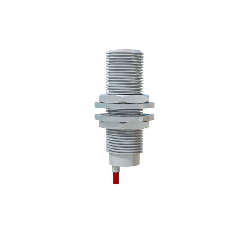
Electrical interference and mutual interference between multiple sensors pose significant risks. To mitigate electrical noise, always use shielded cables and ground the shield properly at the control panel, leaving it ungrounded at the sensor end to prevent ground loops. Maintain adequate separation between sensor cables and high-voltage power lines. When mounting multiple sensors in close proximity, mutual interference can occur, causing erratic behavior. A general rule is to maintain a lateral spacing of at least two times the sensor diameter between adjacent units. If side-by-side mounting is unavoidable, sensors can be staggered in depth or operated on alternating cycles if possible.
For non-cylindrical sensors, such as rectangular capacitive or ultrasonic sensors, mounting typically involves brackets or direct bolting. Ensure the bracket is rigid and does not flex under operational stress, as this can alter the sensing field alignment. The mounting surface should be clean and flat. For capacitive sensors, which detect materials based on dielectric constant, it is critical to secure the sensor body stably and minimize movement relative to the background or the mounting surface, as this can cause drift in the sensitivity setting.
Finally, post-installation verification is a non-negotiable step. After securing the sensor, perform a functional test by moving the target through its expected path at operational speeds. Measure the actual sensing distance to confirm it aligns with specifications under real conditions. Check for any signs of physical contact between the target and the sensor face. Document the installation details, including torque values, spacing, and orientation, for future maintenance reference.
Adherence to these mounting principles transforms a proximity sensor from a simple component into a reliable and precise data point for the control system. Investing time in correct installation prevents recurring problems, enhances system safety, and maximizes the return on investment in automation technology.