Capacitive proximity sensors are widely used in industrial automation for detecting non-metallic objects, liquid levels, powder materials, and transparent films. Unlike inductive sensors, they operate based on changes in capacitance caused by the presence of any material that alters the dielectric constant near the sensing face. Proper calibration and debugging are critical to ensure reliable performance, especially in challenging environments with humidity, temperature fluctuations, or electrical noise. This guide outlines systematic steps for calibrating and troubleshooting capacitive sensors in industrial applications.
First, ensure the sensor is correctly installed. Mount the sensor securely, maintaining the recommended sensing distance (usually specified as Sn in datasheets). Avoid mounting near conductive surfaces or moving parts that could cause false triggers. The sensing area should be free of obstructions, and the target object must pass within the nominal sensing range. For level detection applications, ensure the sensor is positioned to avoid material buildup on the sensing face, which can lead to drift or permanent activation.
Power supply considerations are paramount. Most capacitive sensors operate on DC (10-30V) or AC (20-250V) voltages. Verify the voltage matches the sensor rating and use a stable, regulated power source. Voltage spikes or drops can cause erratic behavior. Implement surge protection if the sensor is connected to inductive loads like relays or motors. Always follow the wiring diagram: typically, brown wire to positive, blue to negative, and black as the output signal. For AC models, connect the load in series with the output line.
Calibration involves adjusting the sensitivity potentiometer, usually located on the back or side of the sensor. Start by placing the target object at the desired detection distance. Turn the potentiometer clockwise to increase sensitivity (counterclockwise to decrease) until the output LED indicates detection. Then, fine-tune by moving the target slightly beyond the nominal range; the sensor should deactivate. Repeat this process to establish a stable threshold. For applications involving varying material densities (e.g., different plastic types), calibrate with the material that has the lowest dielectric constant to avoid false triggers.
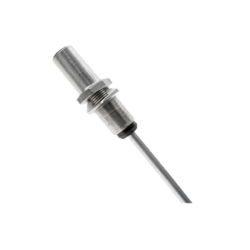
Environmental factors significantly impact performance. High humidity or condensation can increase baseline capacitance, causing false positives. In such cases, reduce sensitivity or use sensors with environmental compensation features. Temperature changes may affect the oscillator circuit inside the sensor; allow a warm-up period after power-on. Electrical noise from nearby frequency drives or welding equipment can interfere with the sensor’s internal oscillator. Shielded cables, proper grounding, and physical separation from noise sources are essential. Ferrite cores on cables may suppress high-frequency interference.
Troubleshooting common issues requires a methodical approach. If the sensor fails to detect objects, check power connections and voltage levels. Use a multimeter to verify output signal continuity. Inspect the sensing face for contamination like dust, oil, or moisture, which can attenuate the electric field. Clean with a soft cloth and isopropyl alcohol if needed. For intermittent operation, evaluate target size and material; smaller or low-dielectric targets may require higher sensitivity. Ensure the target moves perpendicularly to the sensing face for optimal coupling.
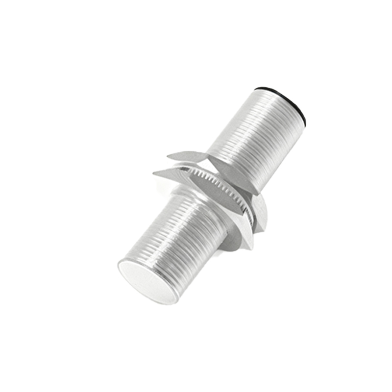
False triggering often stems from external influences. Metallic objects or conductive fluids near the sensor can act as unintended targets. Increase the mounting distance from surrounding structures or install non-conductive barriers. If the sensor latches on permanently, it may be oversensitive or affected by material adhesion. Reduce sensitivity and consider using a sensor with a built-in time delay function to ignore transient disturbances. For networked systems, verify PLC or controller input modules are compatible with the sensor’s output type (PNP/NPN, NO/NC).
Advanced debugging tools like oscilloscopes can analyze the sensor’s output waveform for anomalies such as noise or signal dropouts. Monitor the response time to ensure it meets application requirements, especially for high-speed detection. Regularly log performance data to predict maintenance needs. In summary, successful capacitive sensor deployment hinges on precise calibration, environmental adaptation, and proactive troubleshooting. By adhering to these practices, engineers can enhance system reliability, reduce downtime, and extend sensor lifespan in diverse industrial settings.