In industrial automation, integrating laser sensors with Programmable Logic Controllers (PLCs) is a critical task for achieving precise control and monitoring. Proper wiring ensures reliable communication between the sensor and PLC, minimizing downtime and enhancing system efficiency. This guide outlines the fundamental principles, steps, and best practices for wiring a laser sensor to a PLC, tailored for engineers and technicians in the field.
Laser sensors are widely used for applications such as object detection, distance measurement, and positioning due to their high accuracy and fast response times. Common types include diffuse reflective, through-beam, and retro-reflective sensors, each with specific wiring requirements. Typically, these sensors operate on DC voltage (e.g., 12-24V DC) and provide digital or analog outputs. Digital outputs (e.g., PNP or NPN) are often used for simple on/off signals, while analog outputs (e.g., 0-10V or 4-20mA) transmit continuous data, such as distance values.
Before starting the wiring process, gather necessary components: the laser sensor, PLC (e.g., Siemens, Allen-Bradley, or Mitsubishi models), power supply, cables, and connectors. Always refer to the sensor and PLC manuals for specific pin configurations and voltage ratings. Safety is paramount—ensure the system is powered off and follow lockout/tagout procedures to prevent electrical hazards.
Step-by-Step Wiring Procedure:
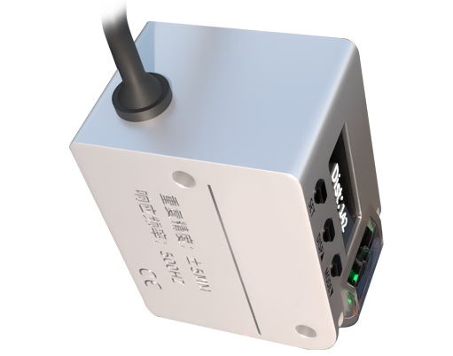
1. Power Connection: Connect the sensor’s power terminals. Typically, the sensor has two power wires: positive (+) and negative (-). For a 24V DC sensor, link the positive wire to the DC power supply’s positive terminal and the negative wire to the supply’s negative terminal. Verify the voltage matches the sensor’s specifications to avoid damage.
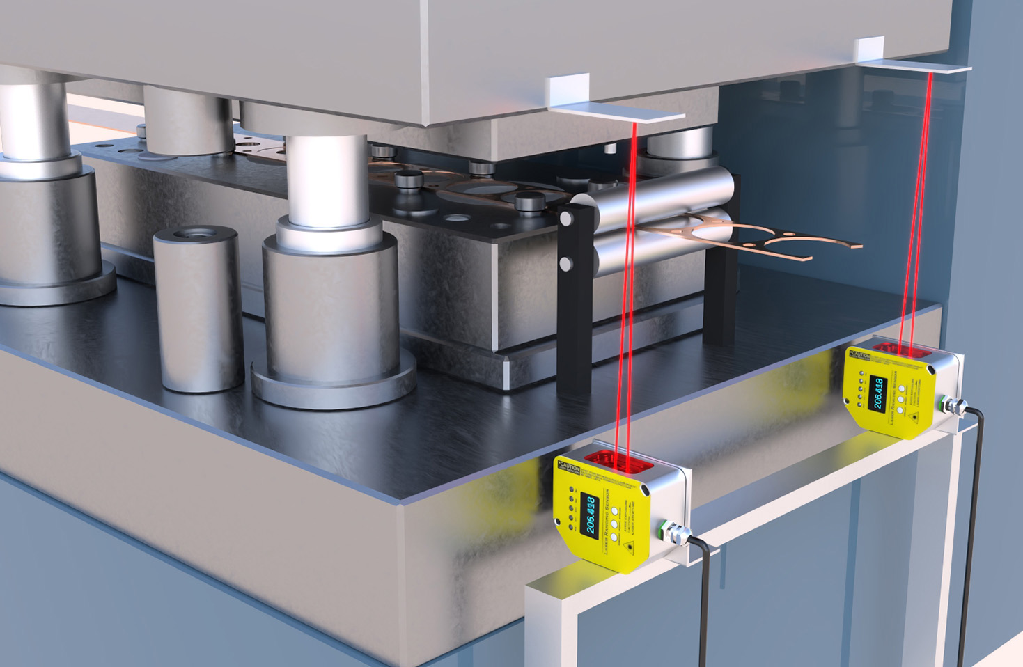
2. Output Connection: Identify the sensor’s output type. For a digital PNP sensor (sourcing output), the output wire provides a positive voltage when activated. Connect this wire to a digital input module on the PLC. For example, wire the sensor output to an input point like I0.0 on a Siemens PLC, and link the PLC input’s common terminal to the power supply negative. For NPN sensors (sinking output), the output sinks current to ground; connect the output to the PLC input, with the PLC input common tied to positive voltage.
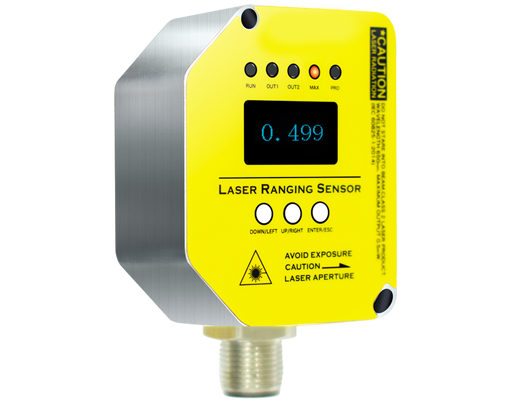
3. Analog Output Wiring: If using an analog sensor, connect the output wire (e.g., for 4-20mA) to an analog input module on the PLC. Shielded cables are recommended to reduce electromagnetic interference. Ground the shield at one end, typically at the PLC side, to prevent noise.
4. PLC Configuration: After wiring, configure the PLC program. Set the input addresses in the software (e.g., TIA Portal for Siemens or RSLogix for Allen-Bradley). For analog sensors, scale the input values in the PLC to convert raw data (e.g., 0-27648 for 4-20mA) into engineering units like millimeters.
5. Testing and Troubleshooting: Power on the system and test the sensor. Use a multimeter to check voltage levels at connections. Common issues include incorrect polarity, loose wires, or misconfigured PLC addresses. Ensure the sensor’s indicator LED activates upon detection, and monitor the PLC input status in the software.
Best Practices for Reliable Operation:
- Use high-quality, industrial-grade cables and connectors to withstand harsh environments.
- Implement proper cable management, such as conduits or cable trays, to protect wires from physical damage.
- Adhere to EMI/RFI mitigation techniques: keep sensor cables away from high-voltage lines, use twisted-pair cables for analog signals, and ensure grounding is consistent.
- Regularly inspect connections for corrosion or wear, especially in humid or dusty settings.
- Document the wiring diagram and PLC program for future maintenance and troubleshooting.
Advanced Considerations: For complex systems, integrate multiple sensors via network protocols like IO-Link, Profinet, or EtherNet/IP. These protocols simplify wiring by allowing sensors to communicate digitally over a single cable, reducing installation time and enabling advanced diagnostics. Always verify compatibility between the sensor, PLC, and network modules.
In summary, wiring a laser sensor to a PLC involves careful attention to power, output types, and PLC integration. By following standardized procedures and safety guidelines, engineers can ensure robust and efficient automation systems. As technology evolves, leveraging smart sensor networks can further optimize performance, making wiring more streamlined and intelligent.