Proximity sensors are indispensable components in modern industrial automation, playing a critical role in object detection, position sensing, and machine safety without physical contact. When a proximity sensor fails, it can lead to costly production downtime, safety hazards, and quality control issues. Understanding how to diagnose and potentially repair a damaged sensor is a valuable skill for any maintenance technician or electrical engineer. This guide outlines a systematic approach to troubleshooting and repairing common proximity sensor failures.
The first and most crucial step is accurate diagnosis. Never assume a sensor is irreparably damaged without proper testing. Begin by verifying the symptoms. Is the sensor failing to detect objects entirely, providing intermittent signals, or triggering falsely? Check the operational environment for obvious culprits: excessive buildup of metal chips, dust, or coolant on the sensing face can impede performance. Ensure the target object is within the sensor's specified sensing range and is of the correct material and size.
Next, conduct a thorough electrical inspection. With the power locked out and tagged out (LOTO), examine the sensor's housing for physical damage such as cracks, dents, or signs of impact. Inspect the cable and connector for cuts, abrasions, or pinch points. A common point of failure is where the cable enters the sensor housing; stress here can break internal wires. Use a multimeter to check cable continuity. For a 3-wire DC sensor, disconnect it from the controller. Check continuity between the brown wire (typically +V) and the blue wire (typically 0V or common) – there should be a high resistance. Check between the black wire (output) and the blue wire; resistance will vary based on the output state (PNP vs. NPN) but a short circuit indicates internal damage.
Power the sensor in a controlled, safe manner. Using a bench power supply set to the sensor's rated voltage (e.g., 24V DC) is ideal. Connect the supply to the correct terminals. Observe the sensor's indicator LED (if present). When no target is present, the LED should be off (for normally-open models) or on (for normally-closed). Introduce a valid target to the sensing face. The LED state should change, and the output voltage should switch. Measure the output voltage with the multimeter. A PNP sensor should switch from near 0V to near the supply voltage when activated. An NPN sensor should switch from near supply voltage to near 0V. If the LED behaves correctly but the output voltage does not change, the output switching transistor or circuit is likely faulty.
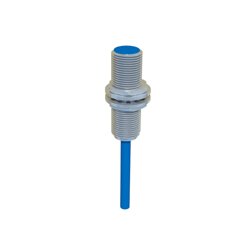
If the sensor has a threaded barrel, internal repair is often impractical due to epoxy potting, which protects the internal oscillator and amplifier circuits from moisture and vibration. For potted sensors, repair is typically limited to the cable. If the cable is damaged near the connector or along its length, it can be replaced. For sensors with integral cables, you can carefully cut the cable a few inches from the housing, strip the wires, and solder on a new cable of the same gauge and type, ensuring excellent insulation and strain relief. For sensors with quick-disconnect connectors, simply replacing the cable assembly is the best fix.
For some larger or non-potted inductive or capacitive sensors, the coil or sensing element might be accessible. However, this requires careful disassembly. If the internal coil is broken or the oscillator circuit component (like a capacitor) is visibly burnt, replacement might be possible if you have an identical donor sensor for parts. This is a specialized repair and not always reliable. Contamination inside the housing, such as from coolant ingress, can sometimes be cleaned with isopropyl alcohol and the unit reassembled with a new sealant, but long-term reliability may be compromised.
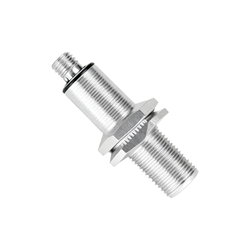
Calibration is another aspect, particularly for analog or specialized sensors. If a sensor's sensing distance has degraded, it may not be a hardware fault but require recalibration, if the model allows it. Refer to the manufacturer's datasheet for calibration procedures, which often involve adjusting a potentiometer.
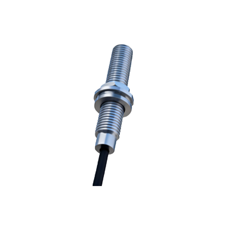
Prevention is the best repair. Ensure sensors are correctly installed with proper mounting brackets to avoid vibration and misalignment. Use protective guards or coatings in harsh environments to shield against physical impact and chemical splashes. Implement regular preventive maintenance schedules to clean sensing faces and check cable integrity.
In conclusion, while many modern proximity sensors are designed as sealed, replaceable units, a logical diagnostic approach can save time and money. Often, the issue is environmental, electrical (wrong wiring, faulty power supply), or a simple cable fault—all of which are repairable. For internally damaged, potted electronics, replacement is usually the most cost-effective and reliable solution. Always prioritize safety, consult the manufacturer's documentation, and when in doubt, replace the sensor to ensure system integrity and personnel safety.