Proximity sensors are fundamental components in modern industrial automation, providing non-contact detection of metallic and, in some cases, non-metallic objects. Their reliability, long service life, and high switching frequency make them indispensable for tasks ranging from simple part presence verification to complex positioning in high-speed machinery. However, the performance and longevity of these sensors are heavily dependent on correct installation. Improper mounting, environmental neglect, or electrical mishandling can lead to erratic operation, premature failure, and costly downtime. This guide outlines the critical installation considerations for inductive, capacitive, and magnetic proximity sensors to ensure optimal system performance.
The first and most crucial step is selecting the correct sensor for the application. Inductive sensors detect ferrous and non-ferrous metals, capacitive sensors detect a wider range of materials including liquids and plastics, and magnetic sensors (reed or Hall effect) detect magnetic fields. Once selected, the installation process begins with mechanical mounting. For cylindrical sensors, ensure the mounting nut is properly torqued according to the manufacturer's specifications to prevent damage to the housing and ensure environmental sealing. Avoid using the sensor body as a mechanical stop; the sensing face should never make physical contact with the target. Flush-mountable sensors can be installed level with a metal surface, while non-flush sensors require a clear, unobstructed area around the sensing face as specified by their "reduced sensing distance" (Sn) guidelines. Always maintain the stated nominal sensing distance (Sn) between the sensor and the target, and account for factors like target material, size, and shape, which can affect the effective range. For example, steel has a correction factor of 1.0, while stainless steel or aluminum may reduce the sensing distance significantly.
Electrical wiring is the next critical phase. Always disconnect power before making connections. Adhere strictly to the wiring diagram provided on the sensor's datasheet or label. Key considerations include: using the correct voltage (DC or AC as specified), observing polarity for DC sensors (typically brown = +V, blue = 0V, black = output), and ensuring proper load current is within the sensor's switching capacity. For 2-wire AC/DC sensors, ensure a minimum leakage current is maintained to keep the sensor active. For 3-wire and 4-wire sensors, connect the shield or drain wire to ground at the control panel end only to prevent ground loops. Use stranded wire of the recommended gauge and protect cables in conduits or cable carriers, especially in areas with moving parts. Keep sensor cables separate from high-voltage power cables and motor leads by at least 10-20 cm to minimize electromagnetic interference (EMI), which can cause false triggering. If crossing is unavoidable, do so at a right angle.
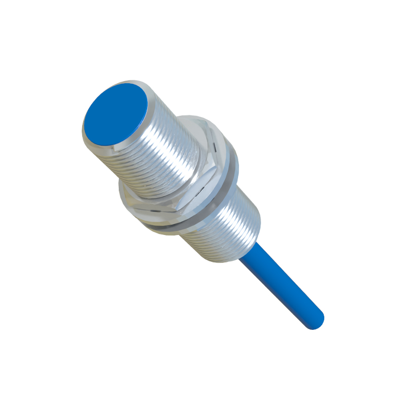
The operating environment presents significant challenges. Proximity sensors are rated with an Ingress Protection (IP) code (e.g., IP67, IP69K). Ensure the rating matches the environment—IP67 for temporary immersion or washdown, IP69K for high-pressure, high-temperature cleaning. Protect sensors from physical impact, excessive vibration, and welding spatter using commercially available protective boots or brackets. Temperature extremes can also affect performance; operate within the specified ambient and sensing face temperature ranges. For high-temperature applications, consider sensors with extended ratings or use a thermal barrier. In corrosive atmospheres, select sensors with housings made of stainless steel (e.g., V4A/AISI 316L) or specially coated plastics.
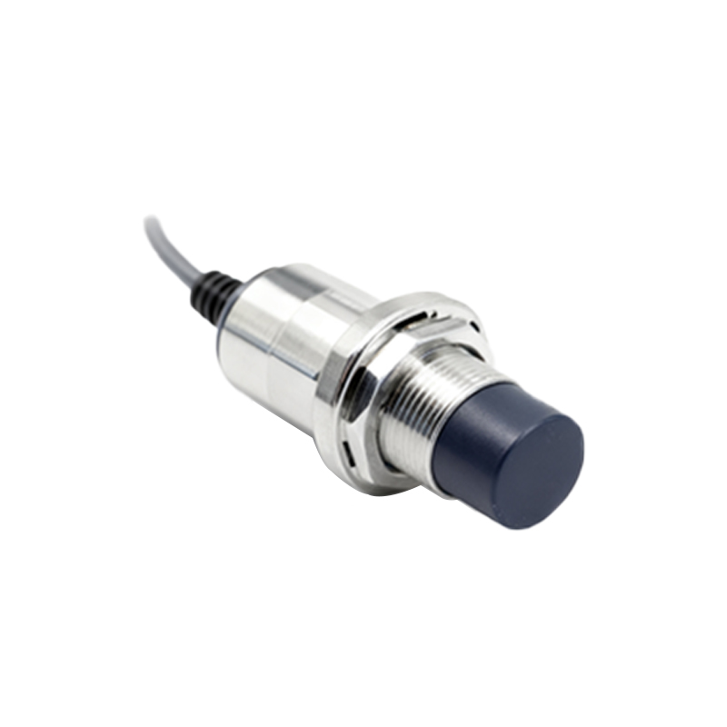
Finally, commissioning and testing are essential. After installation, power the system and verify the sensor's operation with the intended target. Use the sensor's indicator LED (if present) to confirm switching. Check for the influence of surrounding metal (like the mounting bracket or machine frame) by moving the target through its entire operational path. Adjust the sensor's position if necessary to avoid "shadowing" or false signals from adjacent metal. For capacitive sensors, the sensitivity potentiometer may need adjustment to ignore the mounting background or to reliably sense the target material. Document the installation details and establish a routine inspection schedule as part of preventive maintenance.
By meticulously following these installation best practices—correct selection, precise mechanical mounting, careful electrical wiring, environmental protection, and thorough testing—engineers and technicians can maximize the reliability, accuracy, and service life of proximity sensors, thereby enhancing the overall efficiency and uptime of automated industrial systems.