Distance laser sensors are critical components in modern industrial automation, robotics, and precision measurement systems. Their ability to provide non-contact, high-accuracy measurements makes them indispensable. However, like all sophisticated electronic devices, they are susceptible to performance degradation and failure. Proper maintenance and systematic troubleshooting are essential to ensure longevity and reliability. This guide outlines professional practices for maintaining and repairing distance laser sensors.
Regular maintenance is the first line of defense against sensor failure. Begin with a consistent cleaning regimen. The optical lens is the most vulnerable part; dust, oil mist, or debris accumulation can severely attenuate the laser beam, leading to measurement errors or complete signal loss. Use only approved, lint-free swabs and optical-grade cleaning solutions. Never use abrasive materials or compressed air directly on the lens, as this can cause micro-scratches or drive contaminants deeper into the housing. The sensor's housing and mounting should also be inspected for integrity, ensuring it is free from physical damage and securely fastened to prevent misalignment from vibration.
Environmental factors are a primary cause of sensor issues. Verify that the operating environment stays within the sensor's specified ratings for temperature, humidity, and exposure to chemicals. Excessive heat can damage internal electronics and affect laser diode performance, while condensation from high humidity can short-circuit components or fog the lens. If the sensor is used in harsh environments, consider installing protective accessories like air purgers or protective shrouds to create a cleaner local atmosphere around the lens.
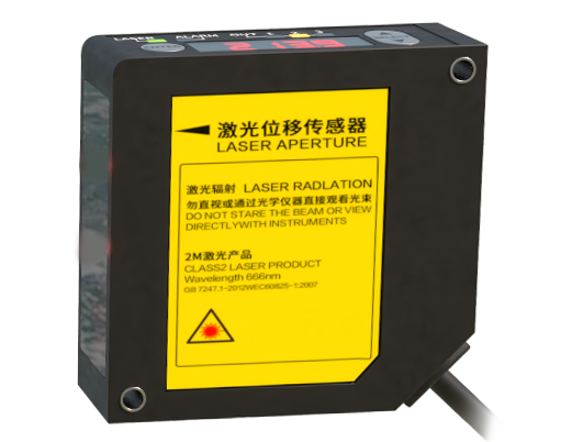
Electrical integrity is another cornerstone of maintenance. Periodically check the power supply for stability and noise. Voltage spikes or ripple can irreparably harm the sensor's sensitive circuitry. Ensure all cable connections are tight and that cables are not frayed, pinched, or stretched. Intermittent faults are often traced back to failing cable insulation or loose connector pins. Use shielded cables, properly grounded, to minimize electromagnetic interference (EMI) from nearby motors, drives, or welding equipment, which can introduce signal noise.
When a sensor malfunctions, a structured troubleshooting approach is vital. Do not immediately assume the sensor is faulty. First, replicate the problem under controlled conditions. Document the exact symptoms: Is there no output signal, an unstable reading, a consistent offset error, or a complete communication failure?
Start with the basics: confirm power is present at the sensor's terminals using a multimeter. Next, perform a visual and functional inspection of the entire measurement chain. Check the target surface properties. A dark, matte, or transparent target will reflect less laser light than a bright, reflective one, potentially causing a weak return signal. Test with a standardized, high-reflectivity target. Inspect for any obstructions in the beam path and ensure the target is within the sensor's specified measuring range.
Use the sensor's built-in diagnostics, if available. Many modern sensors feature indicator LEDs or can communicate status codes via IO-Link or other digital interfaces. A red LED or a specific error code can quickly point to issues like a dirty lens, overload, or internal hardware fault. Consult the manufacturer's manual for code interpretations.
If basic checks yield no results, proceed to signal analysis using an oscilloscope. Monitor the sensor's output signal while observing the target. An unstable waveform often points to electrical noise, while a degraded signal amplitude suggests optical issues. Comparing the observed signal to the known good waveform from the manual can be highly instructive.
For persistent optical or internal electronic faults, calibration or repair may be necessary. Some sensors allow for user recalibration using a known distance standard. Follow the manufacturer's procedure precisely. If internal repair is needed, such as replacing a laser diode or the photodetector array, evaluate the cost and technical complexity. These components are often precisely aligned in the factory. Unless you have specialized optical alignment tools and expertise, attempting a deep internal repair may cause further damage. In many cases, especially with significant internal damage or outdated models, sending the unit to the manufacturer or an authorized service center is the most reliable and cost-effective solution. They have the proprietary software, calibration benches, and spare parts to restore the sensor to its original specifications.
Finally, maintain detailed logs of all maintenance activities, environmental conditions, and any failures. This historical data is invaluable for identifying recurring problems, predicting sensor lifespan, and making informed decisions about sensor selection for future applications. By implementing a proactive maintenance schedule and a methodical troubleshooting protocol, you can maximize the operational uptime and accuracy of your distance laser sensors, protecting your investment and ensuring process integrity.