In the realm of industrial automation, proximity switch sensors are indispensable components for non-contact detection. Among their various sensing modes, the ability to detect permanent magnets is a critical function, enabling reliable position sensing, limit switching, and safety interlocking in countless applications. This article delves into the technical principles, selection criteria, and practical applications of inductive and magnetic proximity sensors when used with sensing magnets.
Technical Principles of Sensing
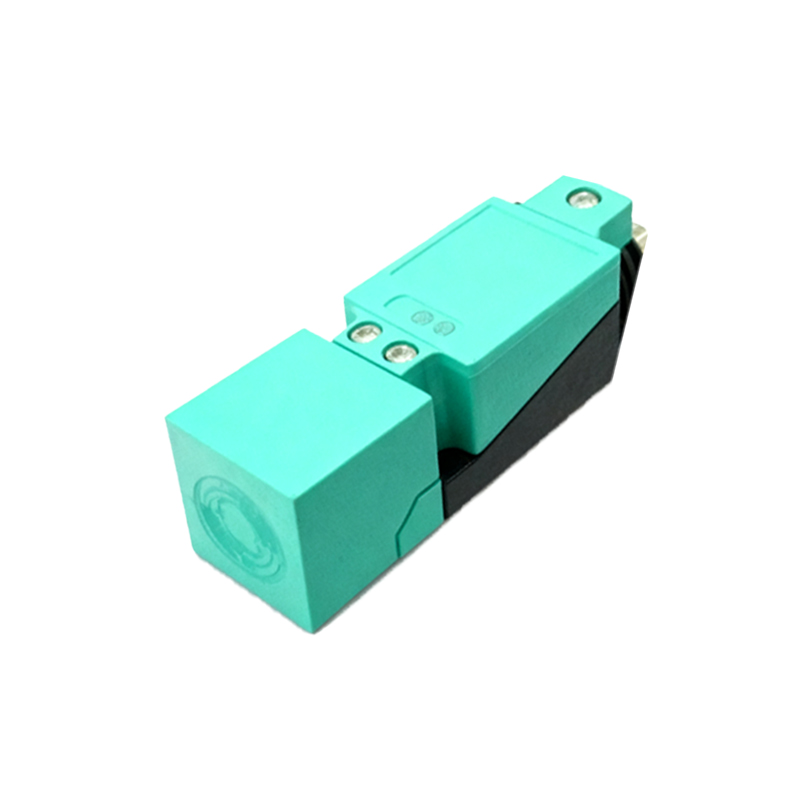
Not all proximity sensors are created equal for magnet detection. The two primary types used are:
1. Inductive Proximity Sensors: These are the most common type. They generate an oscillating electromagnetic field. When a ferrous metal (like iron or steel) enters this field, it causes eddy currents, which dampen the oscillation and trigger the sensor's switch. A standard inductive sensor will not detect a non-ferrous magnet like Alnico or certain rare-earth types if they contain little iron. However, many permanent magnets, especially ferrite and neodymium-iron-boron (NdFeB) magnets, contain sufficient ferromagnetic material to be detected. The sensing distance for a magnet is typically shorter than for a solid piece of steel of the same size due to differences in material composition and eddy current generation.
2. Magnetic Proximity Sensors (Reed Switch or Hall Effect): These are specifically designed to detect magnetic fields.
Reed Switch Sensors: Contain two ferromagnetic reeds sealed in a glass tube. When an external magnetic field from a magnet is applied, the reeds magnetize and attract each other, closing the contact. They are simple, cost-effective, and can be actuated by relatively weak magnetic fields.
Hall Effect Sensors: Semiconductor devices that produce a voltage (Hall voltage) proportional to the strength of an applied magnetic field perpendicular to the current flow. They offer solid-state reliability, high switching frequency, and can detect both the presence and polarity of a magnet. They are ideal for precise position sensing (e.g., in brushless DC motors).
For reliable operation with magnets, magnetic proximity sensors (reed or Hall effect) are explicitly recommended, as their operation is fundamentally based on magnetic flux.
Key Selection Parameters
Choosing the correct sensor-magnet combination requires careful analysis:
Sensor Type: Determine if the application requires simple presence detection (reed switch may suffice) or precise, high-speed detection of field strength/polarity (Hall effect is superior). If the magnet is strongly ferromagnetic, an inductive sensor might be a viable, robust option in harsh environments.
Sensing Distance (Sn): This is the nominal operating distance. It is drastically affected by the magnet's size, grade (magnetic flux density), and orientation. The magnet's poles must be aligned correctly with the sensor's active face. Always consult sensor datasheets for tested sensing distances with magnets, which are usually much shorter than the rated Sn for steel.
Magnet Characteristics: Consider the magnet material (NdFeB, SmCo, Ferrite, Alnico), grade (e.g., N52), dimensions, and polarization direction. A stronger, larger magnet will typically achieve a longer sensing distance. The magnet must be mounted securely to prevent demagnetization from vibration or shock.
Environmental Factors: Temperature extremes can affect both sensor performance and magnet strength (NdFeB magnets are susceptible to demagnetization at high temperatures). Consider IP ratings for dust and water ingress, and the presence of strong external magnetic fields or weld spatter.
Applications in Industrial Automation
The sensor-magnet pairing is ubiquitous due to its reliability and isolation from non-magnetic materials.
Cylinder Position Sensing: A magnet embedded in the piston of a pneumatic or hydraulic cylinder is detected by a sensor mounted on the cylinder body to indicate end-of-stroke positions. This is perhaps the most common application.
Door and Hatch Position Monitoring: Used on machine guards, safety doors, and access panels. The magnet is mounted on the moving door, and the sensor on the frame, providing a non-contact safety interlock.
Rotary Encoding and Speed Detection: Multiple magnets placed on a rotating shaft or gear can be detected by a stationary sensor to measure RPM or index position.
Conveyor Systems: Detecting the position of pallets or carriers that have a magnet attached, used for sorting or stopping at workstations.
Elevator and Lift Systems: For floor leveling and limit switch functions, where non-contact and cleanliness are advantages.
Installation and Calibration Best Practices
1. Alignment: Ensure precise alignment between the magnet's pole axis and the sensor's sensing face. Misalignment can reduce the effective sensing distance by 50% or more.
2