Proximity sensors are indispensable components in modern industrial automation, manufacturing lines, and safety systems. As an electrical engineer, encountering a malfunctioning proximity sensor is a common yet critical challenge. A failed sensor can halt production, cause safety hazards, or lead to product defects. This guide provides a systematic, industry-standard approach to diagnosing and repairing common proximity sensor failures, focusing on inductive and capacitive types prevalent in industrial settings.
The initial step in any repair process is accurate diagnosis. Never assume the sensor is faulty without verification. Begin with a visual inspection. Check for obvious physical damage such as cracks in the housing, bent sensing faces, or severed cables. Look for environmental contaminants like metal shavings, oil buildup, or excessive dust on the active sensing surface, which can severely attenuate the sensing field. Ensure the sensor is properly mounted and aligned; even a slight misalignment can cause intermittent operation, especially in precise positioning applications.
Next, verify the electrical connections. Use a multimeter to check the supply voltage at the sensor's terminals. Ensure it matches the sensor's specifications (commonly 10-30V DC or 90-250V AC). A voltage drop under load might indicate an inadequate power supply or a short circuit elsewhere in the system. Inspect the wiring for loose connections, corrosion, or insulation damage. For 3-wire DC sensors, confirm the correct wiring: brown (or red) to positive (+V), blue to negative (0V), and black (or white) as the output signal. Swapping the brown and blue wires is a frequent installation error that instantly damages the device.
After confirming power and wiring, proceed to test the sensor's output. For a digital output sensor, monitor the output state with a multimeter or a PLC input indicator. Actuate the sensor by introducing a valid target object (e.g., a piece of mild steel for inductive sensors) at the specified sensing distance. Observe if the output switches reliably. For analog output sensors, measure the output current (e.g., 4-20mA) or voltage while varying the target distance. Compare the readings to the sensor's datasheet curve. An erratic or static output often points to internal component failure.
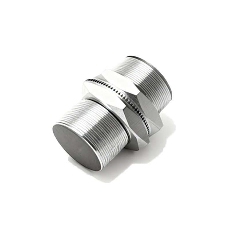
Understanding the failure mode is crucial. Common symptoms include:
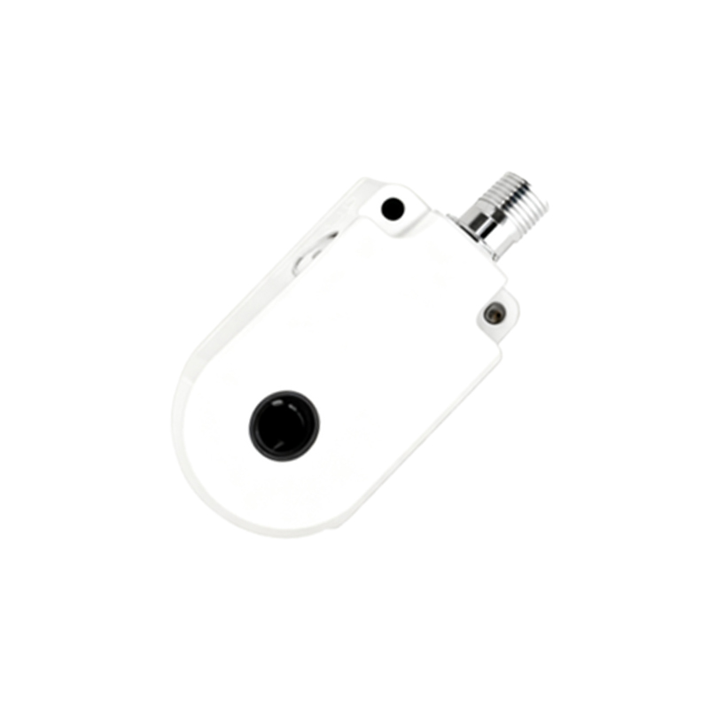
1. No Output: The sensor does not switch regardless of target presence. Causes include complete internal circuit failure, broken coil (inductive), open circuit in wiring, or incorrect power supply.
2. Stuck Output: The output remains permanently ON or OFF. This can be caused by a welded solid-state switch (triac/transistor), a failed output driver IC, or severe sensor overload (e.g., short circuit on the output line).
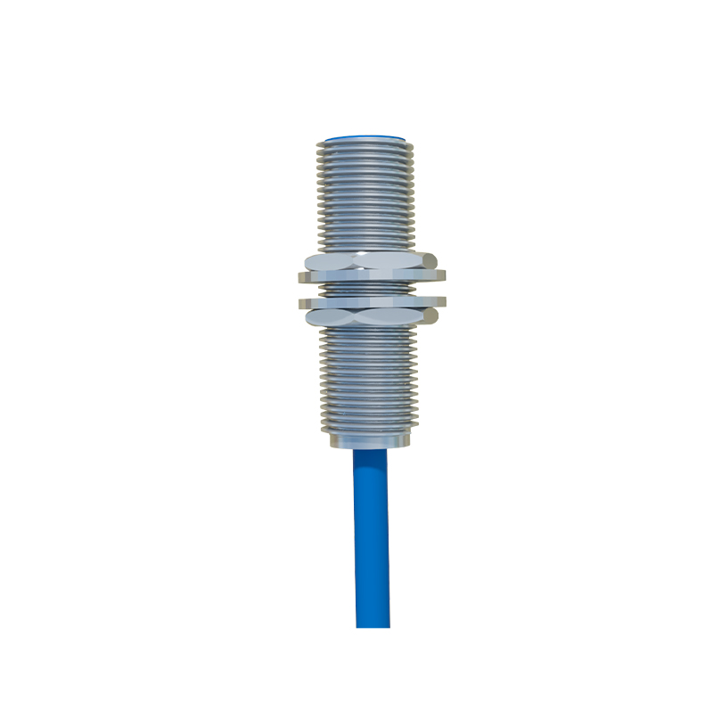
3. Intermittent Operation/Reduced Sensing Distance: The most common issue. Causes are often external: buildup of debris, a weakening power supply, electrical noise interference, or a deteriorating oscillator circuit within the sensor. Temperature extremes can also cause this.
4. False Triggering: The sensor activates without a target. This is typically due to electrical noise from nearby motors, welders, or high-frequency drives (VFDs). Incorrect sensor type selection (e.g., a capacitive sensor detecting a non-metallic container wall) can also be the culprit.
For repairs, many modern industrial proximity sensors are sealed, potted units designed for replacement, not component-level repair. However, for high-value sensors or critical applications, deeper troubleshooting is warranted.
Electrical Noise Mitigation: If false triggering or instability is suspected, implement noise suppression. Use shielded cables, grounding the shield at the controller end only. Install ferrite cores on the sensor cable near the sensor head. Ensure proper separation of sensor cables from high-power AC lines. Power the sensor from a clean, regulated supply. Adding a snubber circuit (RC network) across the load or a metal-oxide varistor (MOV) across the supply terminals can suppress voltage spikes.
Internal Repair Considerations: Warning: This involves opening the sensor housing, voiding certifications (UL, CE), and should only be attempted by qualified personnel on non-safety-critical applications. If the housing is openable, inspect the PCB for burnt components, cracked solder joints, or damaged traces. The oscillator circuit (in inductive sensors) is a common failure point. Check the oscillator coil for continuity. A failed oscillation capacitor or transistor can stop the circuit. For the output stage, test the output switching transistor or triac for shorts or opens. Replacement requires exact or carefully selected substitutes matching voltage, current, and switching speed.
Often, the most cost-effective and reliable solution is sensor replacement. When selecting a replacement, ensure compatibility: sensing type (inductive/capacitive), sensing distance, housing material and size, output type (PNP/NPN, NO/NC, analog