In industrial automation and precision measurement, laser sensors have become indispensable tools due to their high accuracy, reliability, and non-contact operation. Proper hardware configuration is critical to maximizing sensor performance, ensuring system stability, and extending operational lifespan. This article delves into key considerations for optimizing laser sensor hardware setup, covering components, integration, and best practices.
The core of laser sensor hardware includes the emitter, receiver, optical elements, and control circuitry. The emitter typically utilizes laser diodes that produce coherent light beams, with wavelengths ranging from visible red to infrared, depending on the application. For instance, red lasers (around 650 nm) are common in alignment tasks, while infrared lasers (e.g., 905 nm) suit distance measurement in varied lighting conditions. Selecting the appropriate wavelength is essential—shorter wavelengths offer finer resolution but may scatter more in dusty environments, whereas longer wavelengths penetrate better but require sensitive receivers.
Optical components, such as lenses and filters, shape and direct the laser beam. A well-configured lens system focuses the beam to a precise spot size, enhancing measurement accuracy. For example, in thickness gauging, a narrow beam reduces error margins. Filters, like polarizing or bandpass types, minimize interference from ambient light, crucial in outdoor or brightly lit settings. Integrating adjustable optics allows fine-tuning post-installation, adapting to changing conditions without hardware swaps.
Receiver design is equally vital. Photodiodes or CMOS arrays detect reflected light, converting it into electrical signals. High-quality receivers feature low noise amplification and fast response times, enabling detection of minute changes. In dynamic applications like conveyor belt monitoring, a receiver with a sampling rate above 10 kHz ensures real-time data capture. Pairing the receiver with analog or digital output modules—such as 4-20 mA, 0-10 V, or Ethernet interfaces—facilitates seamless integration into PLCs or SCADA systems.

Power supply and environmental factors significantly impact hardware performance. Laser sensors often operate on 12-24 V DC, with stable voltage regulators to prevent drift. In harsh industrial environments, enclosures rated IP67 or higher protect against dust, moisture, and mechanical shocks. Temperature compensation circuits maintain accuracy across ranges from -10°C to 50°C, essential for processes like metal fabrication where thermal expansion occurs.
Mounting and alignment are practical steps often overlooked. Using rigid brackets minimizes vibration-induced errors, while adjustable mounts simplify beam positioning. For triangulation-based distance sensors, the angle between emitter and receiver must be calibrated to the target surface—typically 30-45 degrees for reflective materials. Regular maintenance, including lens cleaning and connector checks, prevents degradation over time.
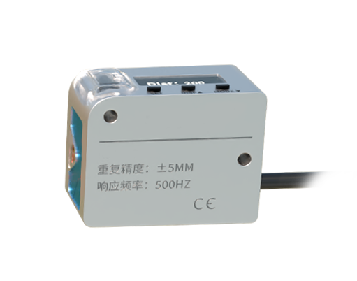
Advanced configurations involve multi-sensor networks or hybrid systems. Combining laser sensors with vision cameras, for instance, enables 3D profiling in robotics. Here, synchronization hardware ensures data coherence, while software algorithms fuse inputs for comprehensive analysis. In safety-critical applications like automated guided vehicles (AGVs), redundant sensors with fail-safe circuits enhance reliability.
Ultimately, optimizing laser sensor hardware requires a holistic approach—balancing technical specs with operational needs. By carefully selecting components, ensuring robust integration, and adhering to industry standards like IEC 60825 for laser safety, engineers can achieve precise, durable solutions that drive efficiency in manufacturing, logistics, and beyond.