Proximity sensors are indispensable components in modern industrial automation, playing a critical role in object detection, positioning, and machine safety without physical contact. However, like any electronic device, they are susceptible to malfunctions. When a proximity sensor fails, it can lead to costly production downtime, safety hazards, and product quality issues. This guide provides a systematic, engineer-level approach to diagnosing and repairing common proximity sensor abnormalities.
The initial step in any repair process is accurate diagnosis. Symptoms of a faulty sensor can vary: intermittent operation, complete failure to detect, constant activation (stuck ON), or erratic behavior. Before disassembling anything, perform a visual inspection. Check for obvious physical damage such as cracks in the housing, bent or broken sensing faces, or loose mounting brackets. Ensure the sensor is securely installed and properly aligned with the target; even a slight misalignment can cause failure, especially in inductive or capacitive sensors. Inspect the cable and connector for cuts, abrasions, or corrosion. Environmental factors are common culprits; verify that the sensor is not exposed to excessive temperatures, moisture, oil immersion beyond its IP rating, or heavy accumulation of metallic dust (for inductive types) or other contaminants.
After the visual check, proceed to electrical diagnostics. The first tool is a reliable multimeter. For a DC 3-wire sensor (PNP or NPN), begin by verifying the power supply. Measure the voltage between the positive (brown wire typically) and negative (blue wire) terminals at the sensor's connector. Ensure it matches the sensor's rated voltage (e.g., 10-30V DC) and is stable, without excessive ripple. A low or fluctuating voltage often points to a power supply issue, not the sensor itself.
Next, test the output signal. For a PNP (sourcing) sensor, connect the multimeter's black lead to the negative supply and the red lead to the output wire (usually black). With no target present, the voltage should be near 0V. Introduce the correct target material (e.g., steel for inductive) to the sensing face at the specified sensing distance. The output voltage should switch to near the supply voltage (e.g., 24V). For an NPN (sinking) sensor, reverse the leads: connect red to positive and black to the output wire. The logic is inverted. A sensor that fails to switch states likely has an internal fault. For a 2-wire AC/DC sensor, measure the voltage drop across the sensor in the ON and OFF states; it should be within the manufacturer's specification.
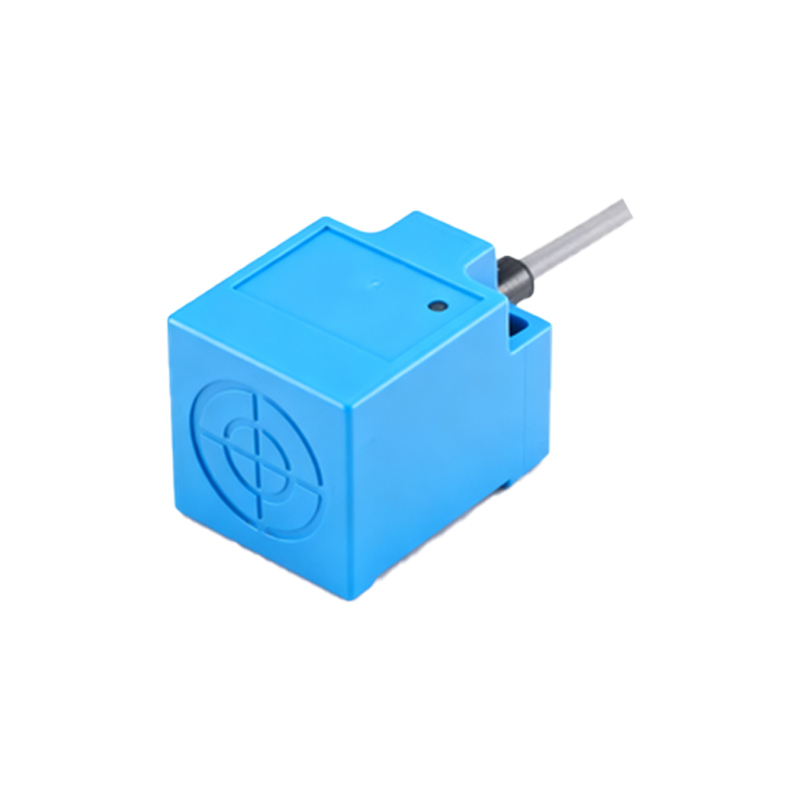
An oscilloscope is invaluable for diagnosing intermittent issues or noise problems. Probe the output line to observe the switching waveform. Look for slow rise/fall times, noise spikes, or chatter (rapid ON/OFF switching), which can indicate a failing output transistor, poor load compatibility, or electrical interference.
If electrical tests confirm the sensor is faulty, repair or replacement is necessary. For sealed, potted, or welded units, repair is often impractical; replacement is the standard procedure. However, for some modular or high-value sensors, limited repairs are possible.
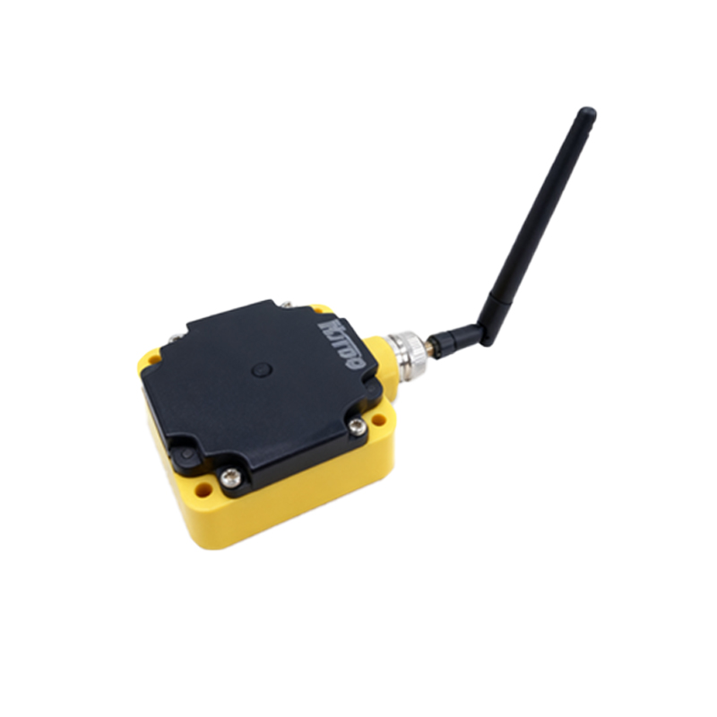
Common Repair Procedures:
1. Connector and Cable Repair: This is the most frequent fix. If the cable is damaged near the connector, cut the cable behind the damaged section, strip the wires, and crimp on a new, compatible industrial connector following the correct pinout. For integral cable sensors with damage close to the housing, a splice may be possible using waterproof solder sleeves and heat-shrink tubing, though this may compromise the IP rating. Always ensure wire gauge and insulation ratings match the original.
2. Cleaning the Sensing Face: Metallic swarf, grease, or paint buildup on an inductive or capacitive sensor's active face can drastically reduce its sensing range. Carefully clean the face with a soft cloth and an appropriate solvent (isopropyl alcohol) that will not damage the epoxy or ceramic coating. Never use abrasive tools.
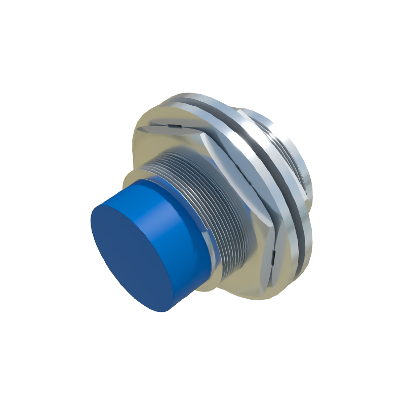
3. Internal Component Replacement (Advanced): In rare cases for expensive sensors, internal components like the output transistor or voltage regulator may fail. This requires carefully opening the housing, which often destroys its environmental seal. Desolder the faulty SMD or through-hole component, identified by visual signs (burn marks, bulging) or in-circuit testing, and replace it with an exact or superior-specification part. This requires advanced soldering skills and schematic knowledge, which is often proprietary.
4. Adjustment and Re-calibration: Some ultrasonic or analog-output sensors have potentiometers for range adjustment or teach-in buttons. If the sensor is physically sound but its sensing distance has drifted, consult the datasheet and use the correct target to re-calibrate it. A non-metallic screwdriver is essential for inductive sensors to avoid influencing the field