Inductive proximity sensors are fundamental components in modern industrial automation and electrical engineering. These non-contact sensing devices operate on the principle of electromagnetic induction to detect the presence or absence of metallic objects without physical contact. As an electrical engineer, a deep understanding of their operation, selection criteria, and application nuances is crucial for designing robust and reliable control systems.
At the core of an inductive proximity sensor is an oscillator circuit that generates a high-frequency electromagnetic field at its active face. This field is emitted from a coil wound around a ferrite core. When a metallic target enters this field, eddy currents are induced on the surface of the target. These eddy currents draw energy from the oscillator, causing a reduction in its amplitude. An internal evaluation circuit, typically a Schmitt trigger, detects this amplitude change and switches the sensor's output state. The output can be either a solid-state transistor (PNP or NMP sourcing/sinking) or a relay contact, providing a signal to a Programmable Logic Controller (PLC), relay, or other control device.
Key specifications define a sensor's suitability for an application. Sensing distance, or 'Sn', is the nominal operating distance for a standard target, usually mild steel. It is critical to note that this distance varies with different metals; for instance, stainless steel may reduce the effective range by 10-30%, while aluminum or copper can reduce it by up to 60%. The hysteresis, a built-in differential between the switch-on and switch-off points, prevents output chatter when a target is at the exact sensing limit. Repeat accuracy, temperature range, switching frequency, and protection class (IP rating) are other vital parameters. Engineers must also consider the housing material (e.g., nickel-plated brass, stainless steel) for chemical resistance and the electrical connection style (pre-wired, quick-disconnect, or M12/M8 connectors).
The advantages of inductive sensors are numerous. Their non-contact nature eliminates mechanical wear, leading to exceptionally long service life. They are immune to ambient light, dust, and non-metallic contaminants like oil or coolant, making them ideal for harsh industrial environments. They offer high switching speeds, suitable for counting or high-speed positioning tasks. Furthermore, they are self-contained, requiring no separate emitter and receiver, simplifying installation.
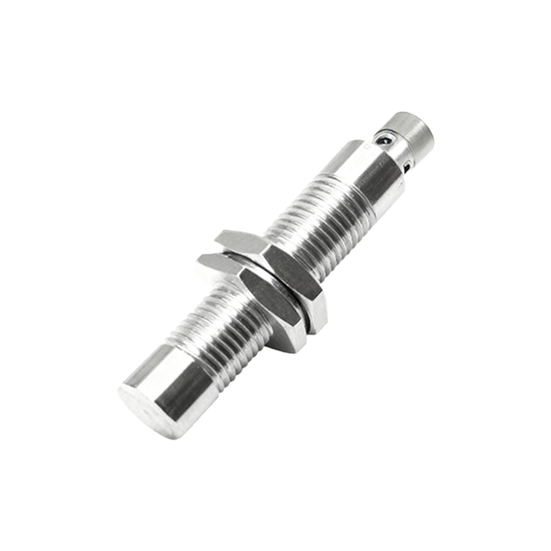
However, limitations exist. Their sole sensitivity to metals is the most significant. They cannot detect plastics, glass, liquids, or other non-metallic materials. The sensing range is relatively short compared to other technologies like ultrasonic or capacitive sensors. The presence of strong electromagnetic fields from nearby motors or welding equipment can cause interference or false triggering. Mounting is also critical; flush-mountable models can be installed embedded in metal, while non-flush types require a clearance zone free of surrounding metal to function correctly.
Application scenarios are vast across manufacturing and processing. Common uses include position verification of machine parts (e.g., cylinder end-position detection), object counting on conveyor belts, monitoring rotational speed via a gear tooth, jam detection, and as a safety interlock to confirm a guard door is closed. In metal machining, they are indispensable for tool breakage detection and workpiece presence confirmation.
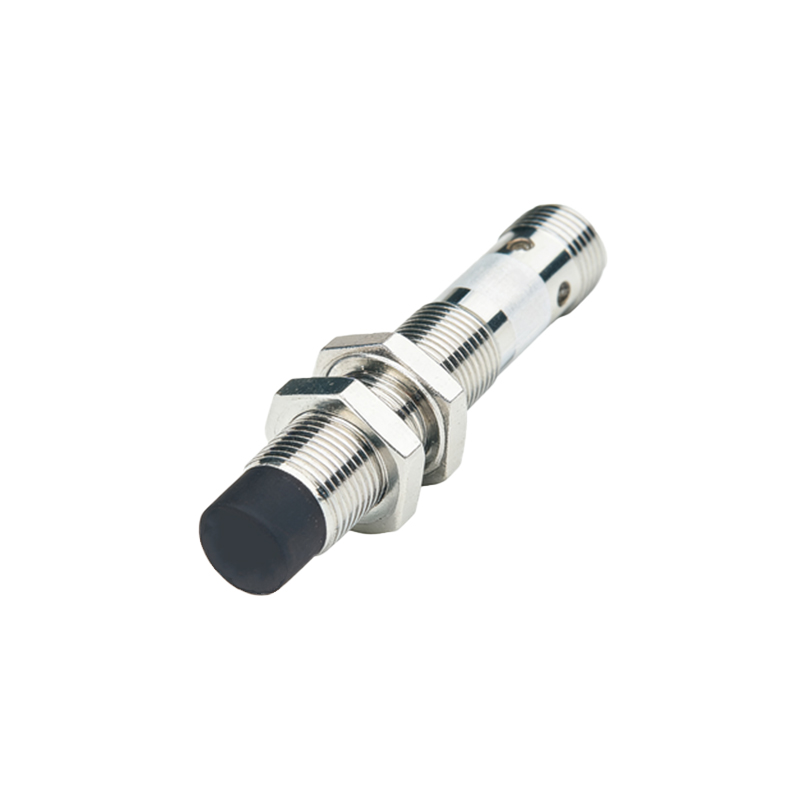
For optimal performance, proper installation and wiring are paramount. Always follow the manufacturer's data sheet for electrical connections, ensuring correct polarity for DC models. Use shielded cables in electrically noisy environments and ground the shield at the controller end only. Maintain the specified mounting distances from other sensors and metal structures. For sensing non-ferrous metals, select a sensor with a factor of 1 (e.g., designed for all metals) or apply a correction factor to the nominal sensing distance. Regular maintenance, though minimal, should include cleaning the sensing face of debris and checking for physical damage.
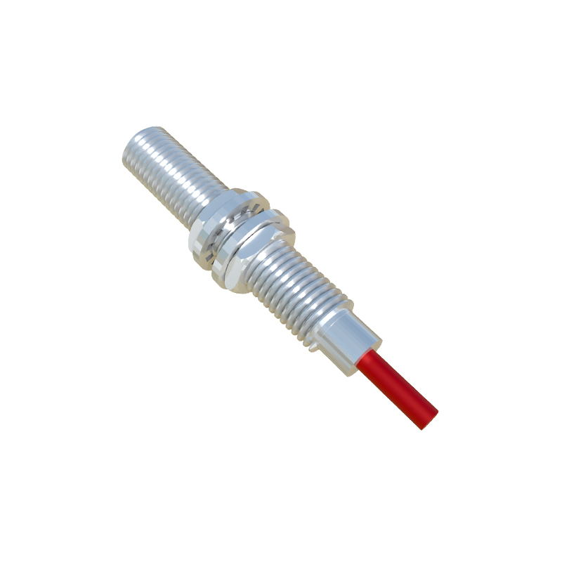
In conclusion, inductive proximity sensors are robust, reliable workhorses of industrial sensing. Their selection and application require careful consideration of the target material, environmental conditions, and electrical requirements. By mastering their principles and practicalities, electrical engineers can effectively integrate these sensors to enhance automation system precision, efficiency, and reliability, forming the sensory backbone of countless modern industrial processes.