Proximity sensors are critical components in modern industrial automation, providing non-contact detection of objects to ensure precise control, safety, and efficiency in machinery. As an experienced electrical engineer, I emphasize that regular inspection and maintenance of these sensors are essential to prevent unexpected downtime and costly repairs. This guide outlines a systematic, step-by-step approach to checking proximity sensors, tailored for professionals in the field.
First, ensure safety protocols are strictly followed. De-energize the equipment and lock out/tag out (LOTO) the power source to prevent accidental activation. Wear appropriate personal protective equipment (PPE), such as insulated gloves and safety glasses. Confirm the work area is clear of hazards before proceeding.
Begin with a visual inspection. Examine the sensor housing for any physical damage, cracks, or signs of corrosion. Check the mounting brackets and connections to ensure they are secure and properly aligned. Look for accumulated dust, debris, or moisture around the sensor, as contaminants can interfere with its operation. Clean the sensing face gently with a soft, dry cloth if necessary, avoiding abrasive materials that could scratch the surface.
Next, verify the electrical connections. Inspect the wiring for fraying, loose terminals, or poor insulation. Use a multimeter to test for continuity in the cables and connectors. Ensure the sensor is correctly wired according to the manufacturer’s diagram—common configurations include PNP (sourcing) or NPN (sinking) outputs, and 2-wire, 3-wire, or 4-wire setups. Incorrect wiring can lead to malfunction or damage to the sensor and control system.
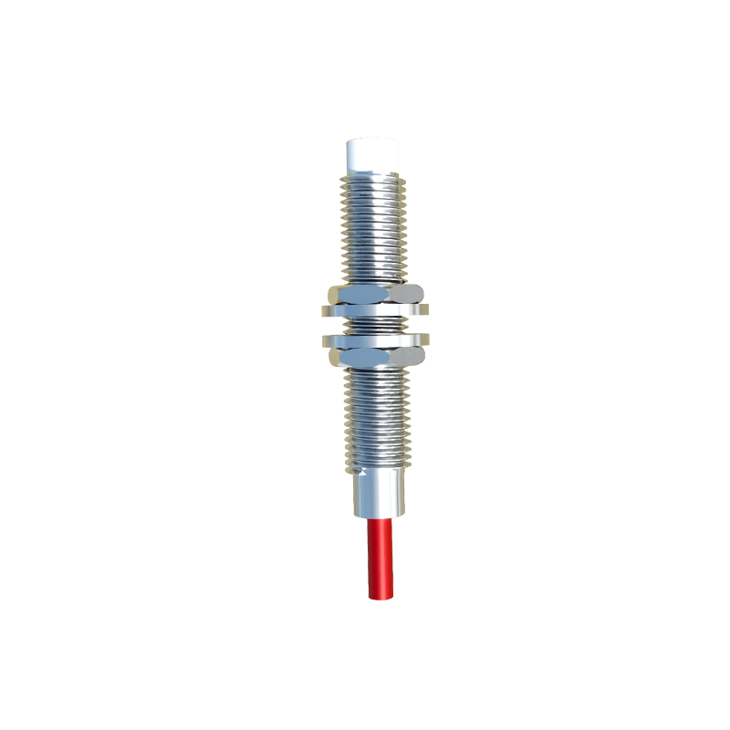
Proceed to power up the system cautiously. Restore power and observe the sensor’s indicator LED, if available. Most proximity sensors have an LED that lights up when an object is detected within the sensing range. If the LED does not illuminate as expected, it may indicate a power issue, faulty sensor, or misalignment. Use a multimeter to measure the supply voltage at the sensor terminals, ensuring it matches the rated voltage (e.g., 10-30 VDC for many models). Fluctuations or deviations beyond tolerance can affect performance.
Test the sensing functionality. Introduce a target object (typically made of the material the sensor is designed to detect, such as metal for inductive sensors) into the sensing range. Move the object slowly toward the sensor and note the point at which the LED activates or the output switches. Compare this detection distance to the sensor’s specified range in the datasheet. A significant reduction in range may suggest wear, aging, or environmental interference. For adjustable sensors, check if the sensitivity potentiometer is correctly set, but avoid unnecessary adjustments unless calibration is required.
Monitor the output signal. Connect an oscilloscope or a logic analyzer to the output terminal to observe the signal waveform. Look for clean, stable switching without excessive noise or delay. Inconsistent signals, such as chatter or false triggers, can be caused by electrical noise, vibration, or incompatible loads. Ensure the load (e.g., a PLC input or relay) is within the sensor’s rated current and voltage limits. If using a programmable logic controller (PLC), verify the input status matches the sensor’s operation through diagnostic software.
Consider environmental factors. Proximity sensors can be affected by temperature extremes, humidity, electromagnetic interference (EMI), or nearby metallic objects. Review the operating conditions against the sensor’s specifications. For instance, high temperatures may reduce sensing distance, while EMI from motors or cables can induce false signals. Shielded cables, proper grounding, and maintaining adequate clearance from other equipment can mitigate these issues.
Document the inspection results. Record any abnormalities, measurements, and corrective actions taken. This log aids in predictive maintenance and troubleshooting future problems. If a sensor fails testing, replace it with a compatible model, ensuring the new unit is installed and calibrated according to guidelines.
In summary, a thorough check of proximity sensors involves safety precautions, visual and electrical inspections, functional testing, and environmental assessment. Regular maintenance, based on the equipment’s operational hours and conditions, enhances reliability. By following these steps, engineers can optimize sensor performance, extend service life, and support seamless industrial automation.