In the realm of industrial automation and electronics, proximity sensors are ubiquitous. They detect the presence or absence of an object without physical contact, enabling countless applications from assembly lines to consumer devices. While commercial sensors offer high reliability, understanding and building a simple one provides invaluable insight into their core principles. This guide walks through constructing a basic inductive proximity sensor, a common type used for detecting metallic objects.
The fundamental principle behind an inductive proximity sensor is electromagnetic induction. It primarily consists of a coil, an oscillator, a detection circuit, and an output stage. When a metallic object enters the sensor's electromagnetic field, eddy currents are induced on the object's surface. These currents draw energy from the oscillator coil, causing a change in its amplitude or frequency. The detection circuit senses this change and triggers the output circuit to switch states.
To build a simple version, you will need the following core components: a ferrite core coil (or you can wind your own with enameled copper wire), a high-frequency oscillator IC like the 555 timer configured in astable mode, a transistor for signal detection (a simple BC547 or 2N2222 will suffice), a comparator IC such as the LM393, an LED for visual indication, a relay or an open-collector output transistor for driving a load, resistors, capacitors, and a DC power supply (typically 5-12V).
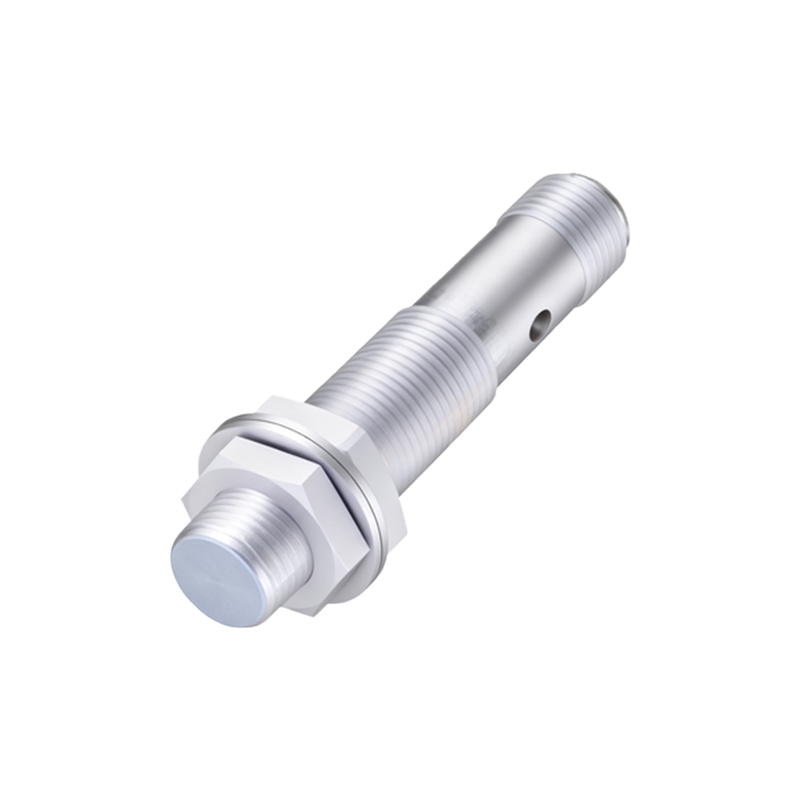
Begin with the oscillator circuit. Configure the 555 timer to generate a high-frequency signal (typically between 100 kHz to 1 MHz). The frequency is determined by the resistor and capacitor values connected to the timer. This oscillating signal is fed to the detection coil. Wind the coil around a ferrite rod or core to concentrate the electromagnetic field. The number of turns and the coil's inductance are critical; start with 50-100 turns and adjust based on performance. This coil forms the sensor's active face.
Next, implement the detection stage. Connect one end of the coil to the oscillator output and the other end to a resistor to ground. The junction between the coil and this resistor is your sensing node. When no metal is present, the oscillator runs at its designed amplitude. When a metal object approaches, the energy loss in the coil causes a drop in the signal amplitude at this node. Feed this node's signal through a transistor amplifier stage to boost the minute change. The transistor's collector output will now show a noticeable voltage shift.
This amplified signal is then sent to the comparator. Set a reference voltage on the comparator's inverting input using a voltage divider. The signal from the detection stage goes to the non-inverting input. When the sensor is idle (no target), the signal voltage is below the reference, and the comparator output is low. When a metal object comes near, the signal voltage rises above the reference, causing the comparator output to switch to a high state. This digital signal is your detection output.
For the output stage, you can connect the comparator's output to an LED (with a current-limiting resistor) for immediate feedback. For practical control, connect it to the base of a power transistor or the input of a relay driver circuit. This allows you to switch an external load like a motor, solenoid, or PLC input. Ensure proper flyback diodes are used if driving inductive loads like relays.
Calibration is crucial. Power the circuit and use a non-metallic screwdriver to adjust the reference voltage potentiometer. The goal is to set the threshold so the output switches reliably at the desired sensing distance. The sensing range for such a homemade sensor is typically short, around a few millimeters to a centimeter, depending on coil size, oscillator power, and target metal.
This simple design has limitations. It lacks the noise immunity, temperature stability, and long-range detection of commercial units. It's primarily sensitive to ferrous metals. However, it perfectly demonstrates the core working principle. For more robust designs, one would integrate specialized ICs that contain the entire oscillator, detector, and stabilized power supply in a single package.
Building this circuit provides a hands-on understanding of sensor hysteresis, sensing distance adjustment, and the importance of stable oscillation. It's a foundational project that bridges theoretical knowledge of electromagnetism with practical electronic design, a valuable exercise for any engineer or technician in the field of industrial controls and automation.