In the intricate world of industrial automation and process control, the precise and reliable detection of valve position is paramount. Among the various technologies employed for this critical task, proximity valve position sensors stand out for their non-contact operation, durability, and versatility. These sensors are integral components in ensuring system safety, optimizing process efficiency, and enabling predictive maintenance strategies across industries ranging from oil and gas to water treatment and chemical processing.
At its core, a proximity sensor used for valve position detection operates on the principle of non-contact sensing. It detects the presence or absence of a metallic target—typically the valve stem, actuator shaft, or a specially mounted flag—without any physical contact. The most common technologies utilized are inductive and magnetic sensing. Inductive proximity sensors generate an oscillating electromagnetic field. When a ferrous metal target enters this field, it induces eddy currents within the target, causing a change in the oscillation amplitude. This change is detected by the sensor's circuitry, which then switches its output state. This makes them ideal for detecting standard steel valve components. Magnetic sensors, including reed switches or Hall-effect sensors, react to the presence of a magnetic field, often from a permanent magnet mounted on the moving part of the valve. They are excellent for applications where the target might be non-ferrous or where sensing through non-metallic barriers is required.
The application of proximity sensors for valve position indication is multifaceted. Primarily, they provide discrete feedback, signaling whether a valve is fully open, fully closed, or sometimes in an intermediate position (using multiple sensors). This binary information is crucial for control logic, interlocking systems, and operator interfaces. For instance, a pump start sequence may be interlocked to require confirmation that an inlet valve is fully open. In safety instrumented systems (SIS), such sensors provide vital inputs for emergency shutdown procedures. Beyond simple end-of-travel detection, they are also used for fault detection. A discrepancy between the commanded valve position (from the control system) and the sensed position can indicate issues like actuator failure, stem seizure, or linkage disconnect, triggering an immediate alarm.
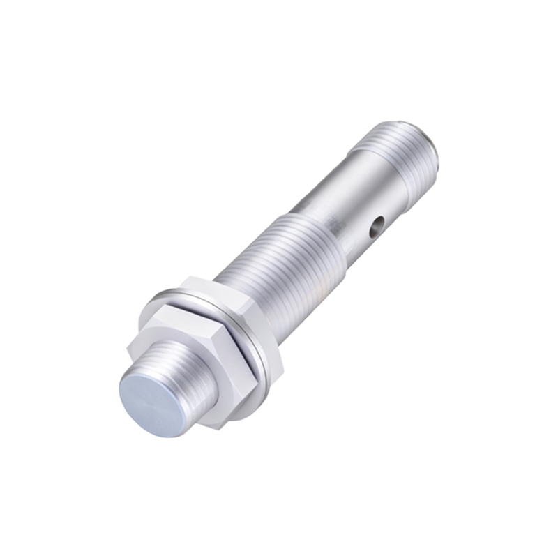
Selecting the appropriate proximity valve position sensor requires careful consideration of several technical and environmental factors. First, the sensing technology must match the target material. For standard steel valves, inductive sensors are robust and cost-effective. For stainless steel, brass, or aluminum valves, or for sensing through a sight glass, a magnetic sensor is necessary. The sensing distance, or nominal range, must be specified with a safety margin to account for mechanical tolerances and potential misalignment during valve operation. Environmental conditions are critical: the sensor's housing and ingress protection (IP) rating must withstand the ambient conditions, which may include exposure to water, chemicals, oils, extreme temperatures, or hazardous areas requiring intrinsically safe or explosion-proof certifications (e.g., ATEX, IECEx). Electrical characteristics are equally important. The output type (PNP/NPN, NO/NC) must be compatible with the programmable logic controller (PLC) or distributed control system (DCS) input card. Supply voltage, current rating, and connection method (pre-wired cable or quick-disconnect) also influence the selection.
Installation and configuration are key to reliable long-term performance. Proper mechanical mounting is essential to ensure consistent alignment between the sensor and its target across the valve's entire range of motion. Sensors should be mounted securely to minimize vibration-induced errors. The air gap between the sensor face and the target should be set according to the datasheet specifications, typically at 50-80% of the nominal sensing distance to account for thermal expansion and mechanical play. Regular functional testing should be incorporated into the maintenance schedule to verify the sensor's response.
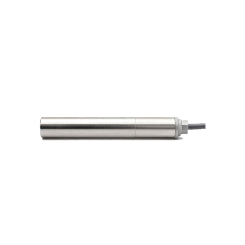
The advantages of using proximity sensors for valve position are significant. Their non-contact nature eliminates mechanical wear, leading to a much longer operational lifespan compared to mechanical limit switches. They offer high switching frequencies and fast response times, suitable for rapidly cycling valves. With no moving parts in the sensing element, they exhibit high resistance to shock, vibration, and contamination. Modern designs are increasingly compact, facilitating installation in space-constrained environments, and many offer LED status indicators for easy diagnostics.
In conclusion, proximity valve position sensors are indispensable tools in modern industrial automation. By providing reliable, non-contact detection of valve stem or actuator position, they form a critical link between the physical movement of process equipment and the digital control system. A thorough understanding of their operating principles, coupled with a methodical approach to selection based on application requirements and environmental challenges, enables engineers to design robust, safe, and efficient valve monitoring systems. As industries continue to embrace Industry 4.0 and the Industrial Internet of Things (IIoT), the data provided by these sensors will further evolve from simple discrete signals to integral components of asset health monitoring and optimized process management.