In industrial automation and control systems, proximity sensors are indispensable components for non-contact detection of metallic or, in some cases, non-metallic objects. A critical performance parameter for these sensors is their nominal sensing distance (Sn), as specified by the manufacturer. However, in real-world applications, engineers frequently encounter a phenomenon known as sensing distance attenuation, where the effective operational range of the sensor is reduced below its rated Sn. Understanding the causes, implications, and mitigation strategies for this attenuation is paramount for ensuring system reliability and preventing costly downtime.
The fundamental operating principle of inductive proximity sensors, the most common type for metal detection, involves an oscillating electromagnetic field generated by a coil in the sensor's face. When a ferrous or non-ferrous metal target enters this field, eddy currents are induced, causing a change in the oscillation amplitude. This change is detected by the sensor's circuitry, triggering an output signal. The rated sensing distance is determined under ideal laboratory conditions using a standard target, typically a square of mild steel (Fe360) with a side length equal to the sensor's face diameter or three times its Sn, whichever is greater. Any deviation from these ideal conditions leads to attenuation.
Several key factors contribute to sensing distance attenuation. The first and most significant is the target material. Inductive sensors are calibrated for mild steel. Other metals have different electrical conductivity and magnetic permeability, which affect eddy current generation. For instance, stainless steel (particularly non-magnetic austenitic grades like 304 or 316) can reduce the effective sensing distance to 60-80% of Sn. Aluminum and copper, being excellent conductors but non-ferromagnetic, may reduce it to 30-50% or even less. Engineers must consult the sensor's correction factor charts, which provide multipliers (e.g., 0.8 for stainless steel, 0.4 for aluminum) to calculate the actual usable range.
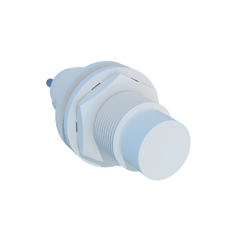
The second major factor is the target size, shape, and orientation. The standard target is a large, flat plate approached axially to the sensor face. Smaller targets, thin foils, wires, or edges of an object present less surface area to interact with the electromagnetic field, resulting in a shorter sensing distance. Similarly, if a flat target approaches at an angle rather than head-on, the effective sensing distance is reduced according to the cosine of the approach angle. A target moving parallel to the sensor face may not be detected at all until it is very close.
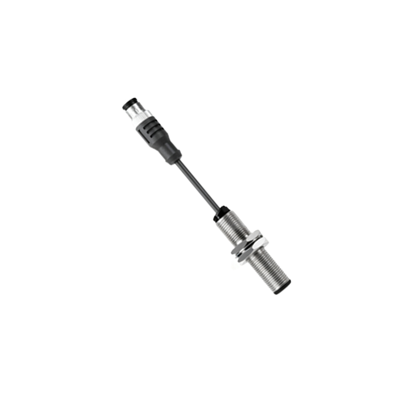
Environmental conditions constitute the third critical category. Extreme temperatures can affect the sensor's electronic components and the properties of the coil, leading to drift. Most industrial sensors are rated for operation between -25°C and +70°C, with derating curves provided for extremes. The presence of strong external magnetic fields, such as those from large motors, transformers, or welding equipment, can interfere with the sensor's own field, causing false triggering or reduced sensitivity. Physical obstructions are also a concern; mounting the sensor flush in a metal bracket (flush mounting) is standard, but if non-ferrous materials are acceptable, non-flush mounting offers a longer range. Crucially, mounting multiple sensors side-by-side can lead to mutual interference if they are not spaced sufficiently apart, as their electromagnetic fields can interact, causing cross-talk and significant attenuation. Manufacturers specify minimum lateral spacing guidelines, often 2-3 times the sensor diameter.
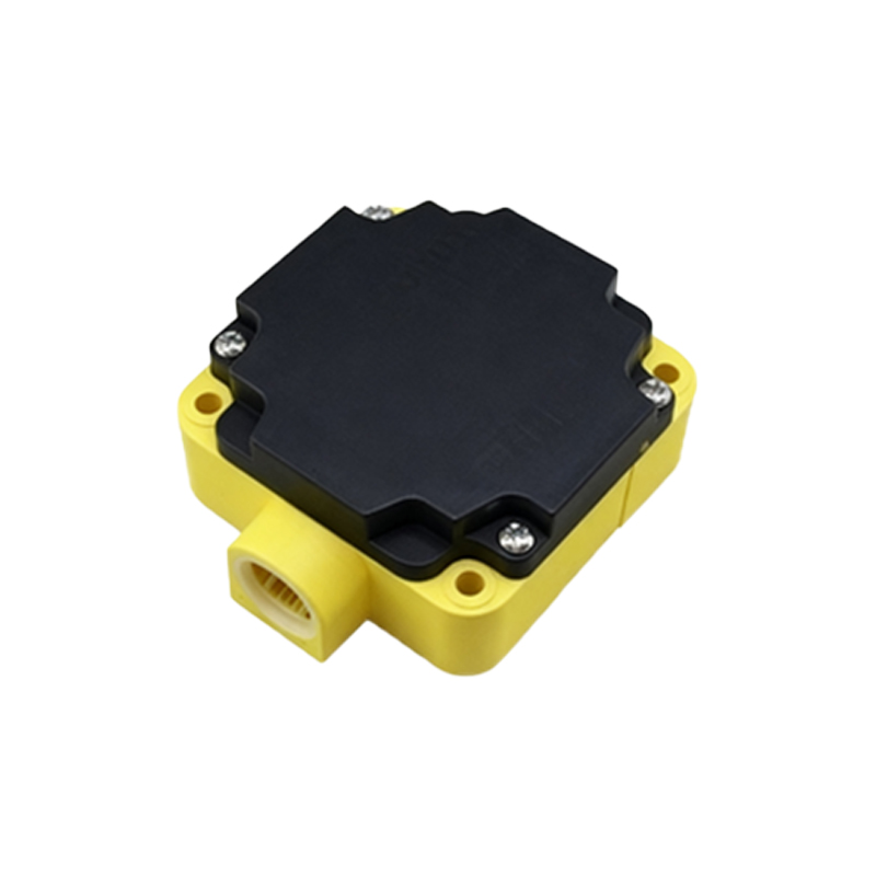
To combat sensing distance attenuation and ensure robust application design, a systematic approach is required. Always begin by applying the material correction factor to the nominal Sn. Next, consider the application's required operating distance (Sa). Industry best practice dictates designing with a substantial safety margin. It is common to use only 60-80% of the corrected sensing distance as the maximum permissible operating point in the application. This derating accounts for variables like supply voltage tolerance (±10%), part-to-part sensor manufacturing variances, temperature effects, and long-term component aging. For critical applications, selecting a sensor with a nominal Sn that is 1.5 to 2 times the required physical gap provides a comfortable safety buffer. Furthermore, pay meticulous attention to mounting guidelines, ensuring proper spacing between sensors and using shielded models in electrically noisy environments. Regular preventive maintenance, including periodic verification of sensing distances under actual operating conditions, can help identify gradual attenuation before it leads to a failure.
In conclusion, proximity sensor sensing distance is not a fixed, guaranteed value but a variable parameter highly dependent on application specifics. Attenuation due to target material, size, environment, and installation is a predictable engineering challenge, not a sensor flaw. By thoroughly analyzing these factors, applying appropriate correction factors and safety margins, and adhering to installation best practices, engineers can design detection systems that are both precise and exceptionally reliable, maximizing uptime and productivity in demanding industrial settings.