In modern industrial automation, achieving high-precision measurement and control is paramount. The integration of laser displacement sensors with Programmable Logic Controllers (PLCs) forms a cornerstone of this capability. This article delves into the technical synergy between these two components, outlining principles, implementation strategies, and best practices for engineers.
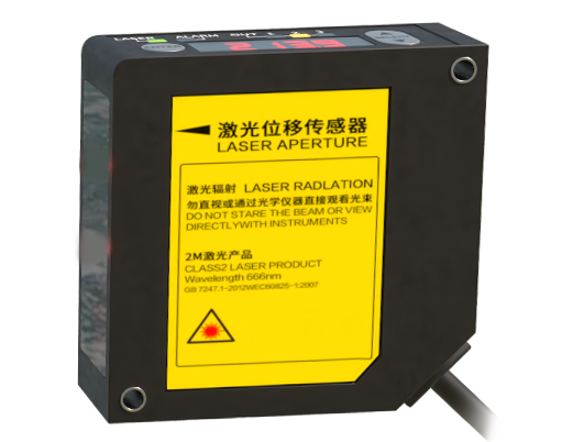
A laser displacement sensor operates on the principle of optical triangulation or time-of-flight measurement. It emits a focused laser beam onto a target surface. The reflected light is captured by a receiving element, such as a CCD or PSD. By analyzing the position of the reflected spot, the sensor calculates the distance to the target with micron-level accuracy. These sensors are prized for their non-contact nature, high speed, and ability to measure a wide variety of materials, including shiny, dark, or transparent surfaces.
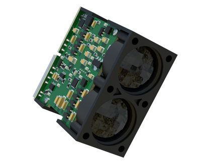
The PLC serves as the industrial brain, executing control logic based on input data. When a laser sensor is connected, it provides the PLC with critical real-time positional data. The connection is typically established via standard industrial communication protocols. Analog interfaces (4-20 mA or 0-10 V) are common for simple setups, where the sensor's output voltage or current is directly proportional to the measured distance. For more complex systems requiring higher data throughput and configuration capabilities, digital interfaces are preferred. These include:
* PROFIBUS DP & PROFINET: Widely used in European automation.
* EtherNet/IP: Common in North American markets.
* Modbus TCP/IP: A simple, open protocol for Ethernet networks.
* DeviceNet & CC-Link: Popular fieldbus options.
Digital communication allows not only for data transmission but also for remote parameterization of the sensor (e.g., setting measurement windows, filtering, and output scaling) directly from the PLC programming software.
The programming logic within the PLC processes the incoming sensor data. This involves several key steps:
1. Data Acquisition & Scaling: The raw input value (from an analog module or a communication word) is converted into a meaningful engineering unit (e.g., millimeters) using scaling functions.
2. Filtering & Validation: To ensure signal stability, software filters (like moving averages) are applied. Logic checks are implemented to validate data, ignoring readings during sensor error states or out-of-range conditions.
3. Comparison & Decision Making: The processed distance value is compared against preset tolerances or reference positions. Based on this comparison, the PLC triggers control actions. For example, in a sorting application, if a measured part height deviates from the nominal value, the PLC can activate a reject mechanism.
4. Closed-Loop Control: In advanced applications like web tension control or robotic guidance, the sensor's data feeds into a PID (Proportional-Integral-Derivative) control loop within the PLC. The PLC continuously adjusts an actuator (like a servo motor) to maintain the target position, creating a precise feedback control system.
The benefits of this integration are substantial. It enables 100% inline inspection, improving quality control by detecting minute defects in dimensions, warpage, or presence/absence of components. It boosts productivity through high-speed measurement, allowing for faster production cycles. Furthermore, the non-contact measurement eliminates wear and tear, reducing maintenance costs and enabling the inspection of delicate or hot objects.
For successful implementation, engineers must consider several factors. Sensor selection is critical: choose a model with appropriate measurement range, resolution, spot size, and response time for the application. Environmental factors like ambient light, dust, steam, or vibrations must be mitigated, potentially requiring protective housings or specific sensor models with robust designs. Proper electrical installation, including correct shielding and grounding of cables, is essential to prevent electromagnetic interference (EMI) from corrupting the sensitive analog or digital signals. Finally, comprehensive testing and calibration under real operating conditions are necessary to validate system accuracy and reliability.
In conclusion, the marriage of laser displacement sensor technology with the robust control capabilities of the PLC creates a powerful tool for industrial automation. It empowers systems with precise, reliable, and high-speed measurement-driven control. As Industry 4.0 advances, this integration will become even more seamless with smarter sensors offering integrated IO-Link functionality for simplified parameter management and diagnostics, further solidifying its role as a fundamental building block for intelligent manufacturing.