In the realm of industrial automation, the precise and reliable detection of objects is paramount. Square proximity sensors, known for their robust construction and consistent performance in harsh environments, are a cornerstone of modern control systems. However, their effectiveness is not solely determined by their intrinsic specifications; the installation position is a critical, often underestimated, factor that directly influences sensing range, reliability, and system longevity. This article delves into the key principles and best practices for determining the optimal installation position for square proximity sensors.
The fundamental operating principle of inductive proximity sensors—the most common type in square housings—is based on generating an electromagnetic field. When a metallic target enters this field, it induces eddy currents, causing a change in oscillation amplitude that is detected by the sensor. The shape and strength of this electromagnetic field, known as the sensing field, are not uniform. For a square sensor, the field typically extends from the active face in a conical or slightly rectangular pattern. The nominal sensing distance (Sn) specified in datasheets is defined under ideal conditions: a standard target (usually mild steel) of a defined size, positioned axially to the face. Any deviation from these conditions affects the actual usable sensing distance.
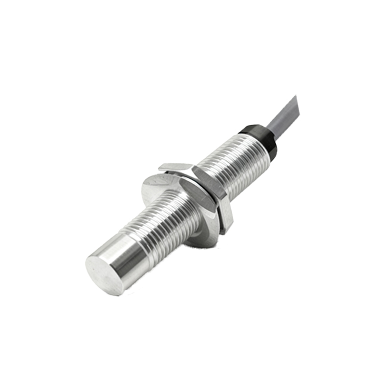
The primary consideration for installation is the mounting position relative to the target's path. The most straightforward and recommended method is axial alignment. Here, the target approaches the sensor head-on, perpendicular to the active face. This position ensures the maximum and most consistent sensing distance. The target should be large enough to cover the active face area completely as it approaches to guarantee a stable switch signal. For smaller targets, the effective sensing distance may be reduced.
In many applications, lateral or sideways detection is necessary due to space constraints or machine design. When a target passes parallel to the sensor face, the effective sensing distance is significantly reduced, often to 50-60% of the nominal Sn. It is crucial to conduct tests with the actual target material and size to verify reliable detection in this orientation. The sensor should be positioned so that the target's leading edge enters the sensing field smoothly, avoiding graze conditions that might cause signal chatter.
Environmental factors dictate the second major set of rules. Proximity sensors, while rugged, can be affected by external metallic influences. A fundamental rule is to maintain adequate clearance distances. This includes mounting the sensor away from surrounding metal structures, brackets, or moving machine parts. A general guideline is to maintain a lateral clearance of at least one sensor width from adjacent metal and a distance of 2-3 times the sensor's depth from any background metal behind the active face. Failure to observe these clearances can lead to a reduced sensing range, false triggering, or even permanent damping of the sensor output.
For sensors mounted flush in metal, the surrounding material can dampen the electromagnetic field. Most square sensors are designed for non-flush mounting, meaning they require the specified clearance around their sides to achieve their full sensing range. Attempting to mount them flush in a metal panel without proper recess will severely impair performance. Some models are rated for flush installation, but this is explicitly stated in their specifications.
The physical stresses on the sensor and cable must also be considered. The installation position should minimize exposure to direct impact, excessive vibration, and abrasive materials. While square sensors often have high IP ratings (e.g., IP67, IP69K), protecting them from physical damage extends service life. Cable strain relief is mandatory; the cable should not bear the weight of the sensor or be subjected to sharp bends, especially at the gland entry. In applications with heavy vibration, additional bracketing may be necessary to prevent loosening of the mounting hardware.
Electrical interference is another concern. While proximity sensors are generally immune to ambient light, they can be susceptible to electromagnetic interference (EMI) from high-power cables, motors, or frequency drives. Where possible, sensor cables should be routed separately from power lines, preferably in dedicated cable ducts or conduits. If crossing is unavoidable, it should be done at a 90-degree angle to minimize inductive coupling.
In summary, the optimal installation of a square proximity sensor is a systematic process: First, define the target's material, size, and approach path. Second, select an axial alignment position where possible to maximize Sn. Third, ensure all mandatory clearance distances from surrounding and background metal are respected. Fourth, secure the sensor and cable to withstand the environmental conditions. Finally, always verify the installation by testing with the actual target under all expected operating conditions, including temperature extremes. Adhering to these principles ensures that the square proximity sensor will deliver the reliable, maintenance-free performance that is essential for efficient and safe industrial automation.