Proper installation of proximity sensors is critical for ensuring reliable operation, longevity, and safety in industrial automation systems. These non-contact devices, which detect the presence or absence of an object, are ubiquitous in manufacturing, packaging, and material handling. Incorrect installation can lead to false triggers, reduced sensing range, physical damage, or complete failure. This guide provides a comprehensive, step-by-step approach to installing inductive, capacitive, and photoelectric proximity sensors, adhering to industry best practices.
Step 1: Pre-Installation Planning and Safety
Before handling any sensor, always de-energize the electrical circuit and follow Lockout/Tagout (LOTO) procedures. Confirm the sensor type (e.g., inductive for metals, capacitive for non-metals/liquids, photoelectric for various materials) is suitable for the target object and environment. Review the manufacturer's datasheet for critical specifications: sensing distance (rated operating distance Sn), housing material, voltage range, output type (PNP/NPN, NO/NC), and environmental ratings (IP, NEMA). Ensure you have the correct mounting hardware, tools, and any necessary mounting brackets or accessories.
Step 2: Selecting the Mounting Location
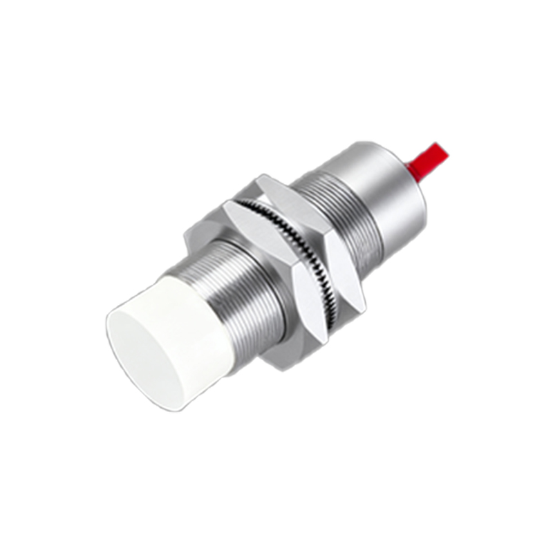
Choose a location that guarantees consistent detection of the target object. For inductive and capacitive sensors, maintain a minimum clearance around the sensing face. The general rule is to allow a space equal to the sensor's diameter on all sides to prevent interference from the mounting nut or surrounding metal (for inductive types). Avoid mounting sensors directly opposite each other to prevent mutual interference. For photoelectric sensors, ensure the optical path is free of obstructions, dust, steam, or highly reflective backgrounds that could cause false readings. Consider vibration, temperature extremes, and potential exposure to chemicals, selecting a sensor with an appropriate ingress protection (IP) rating.
Step 3: Mechanical Mounting
For cylindrical threaded barrel sensors, use the correct locknut. Do not overtighten, as this can distort the housing and affect performance. Typically, hand-tighten plus a quarter to a half turn with a wrench is sufficient. For rectangular or block-style sensors, use the provided slots or holes and secure them firmly to a stable surface using appropriate screws. If using a bracket, ensure it is rigid to minimize vibration transfer. The sensing face must be positioned parallel to the target's approach path for optimal detection. For side-sensing applications, follow the specific orientation guidelines in the manual.
Step 4: Electrical Wiring
Refer to the sensor's wiring diagram, usually found on the device label or datasheet. Key connections include:
Brown wire (BN): Typically connected to the positive DC supply voltage (+V).
Blue wire (BU): Connected to the DC common or 0V.
Black wire (BK): Usually the switched output signal line (for PNP sourcing sensors).
White wire (WH): Often used for output configuration or diagnostic functions.
Use shielded cables in electrically noisy environments, grounding the shield at the controller end only. Keep sensor cables separate from high-voltage power lines to prevent inductive coupling. For AC sensors, correctly identify the Line (L) and Load wires. Always use crimped ferrules on stranded wires for a secure connection in terminal blocks and ensure all connections are tight.
Step 5: Alignment and Adjustment
After powering up the system (following safety re-energization procedures), test the sensor with the target object. Many sensors have a built-in LED indicator that lights up when an object is detected. Fine-tune the sensor's position if necessary. For adjustable sensors (like some photoelectric or ultrasonic types), you may need to set sensitivity or timing functions. Use the manufacturer's recommended procedure, often involving a push-button or potentiometer. The goal is a consistent, stable signal when the target is present within the required range.
Step 6: Functional Testing and Troubleshooting
Conduct thorough testing under normal operating conditions. Check for:
Repeatability: Consistent detection at the same point.
Margin: The target should be well within the effective sensing range, not at its absolute limit.
Immunity: No false triggers from non-target objects, environmental factors, or adjacent machinery.
Common issues include no output signal (check wiring and power), erratic operation (check for electrical noise, insufficient clearance, or dirty sensing face), or reduced range (check for sensor wear or incorrect target material). Always consult the manual for diagnostic LED blink codes.
Conclusion
A methodical approach to proximity sensor installation—encompassing correct selection, careful mounting, precise wiring, and rigorous testing—is fundamental to system reliability. By investing time in proper installation, you minimize downtime, enhance process accuracy, and extend the operational life of