In the realm of industrial automation and precision metrology, line laser sensors have become indispensable tools for non-contact 3D profiling, dimensional inspection, and surface defect detection. While much attention is given to parameters like resolution, scanning speed, and laser class, the strategic selection of the sensor's projection angle—the angle between the laser line and the target surface—is a critical, often nuanced, factor that directly dictates measurement accuracy, system robustness, and application feasibility. This article delves into the engineering principles behind line laser sensor angle optimization, exploring its impact on key performance metrics and providing practical guidance for system integration.
The fundamental operating principle of a line laser sensor, or laser profilometer, involves projecting a thin, focused line of laser light onto a target surface. A camera, positioned at a known triangulation angle relative to the laser emitter, captures the deformation of this line. Any height variation on the surface causes the laser line to shift in the camera's field of view. Through precise calibration and triangulation algorithms, these pixel shifts are converted into accurate height (Z-axis) data, while the camera's movement or the object's motion provides the X and Y coordinates. The core geometry of this setup is defined by the triangulation angle (typically between 15° to 45°) and the angle of incidence of the laser line itself.
The angle of laser incidence is paramount. For ideal diffuse surfaces, a perpendicular (90-degree) incidence is often theoretically optimal as it maximizes signal strength and minimizes optical distortion. However, real-world industrial environments rarely present ideal conditions. Key considerations include:
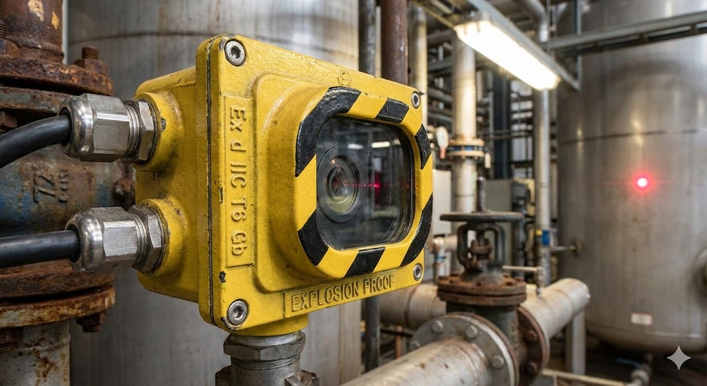
1. Surface Reflectivity and Material: Highly reflective or specular surfaces (e.g., polished metal, mirrors) can cause blinding or saturation of the camera sensor if the laser strikes at a near-perpendicular angle. A shallow incidence angle can direct the intense specular reflection away from the camera's lens, allowing the capture of the useful diffuse component. Conversely, for dark, absorptive materials (e.g., rubber, black anodized aluminum), a steeper angle may be necessary to maximize the amount of scattered light returning to the camera.
2. Surface Geometry and Shadowing: Complex geometries with steep edges, deep grooves, or holes present a challenge known as optical shadowing. If the laser cannot "see" into a recess, or if the camera's view is blocked by a protruding feature, data will be missing. Strategic angling of the laser line, sometimes in conjunction with multiple sensors, is required to illuminate and capture all relevant surfaces. For instance, inspecting a screw thread requires aligning the laser line to run perpendicular to the thread grooves to capture the full profile.
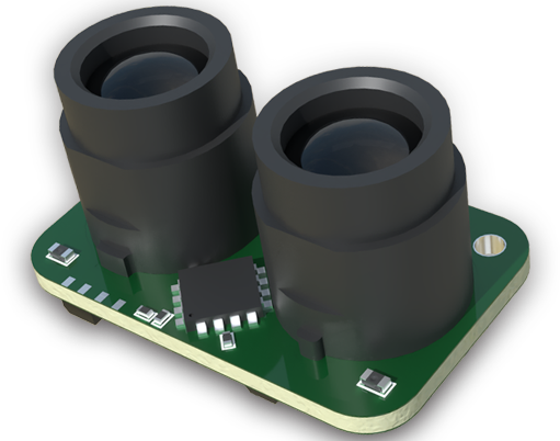
3. Measurement Resolution and Sensitivity: The effective resolution in the height (Z) axis is influenced by the triangulation baseline. A larger triangulation angle generally increases the Z-axis sensitivity—a given height change causes a larger pixel shift. However, this comes with trade-offs: a larger angle increases the footprint of the sensor head, can exacerbate shadowing issues, and may reduce the working distance. The choice is a balance between required Z-axis precision and spatial constraints.
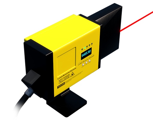
4. Vibration and Standoff Distance: In dynamic environments with vibration, the relative motion between the sensor and target can induce measurement noise. The selection of angle and a sufficient standoff distance (the gap between sensor and target) can mitigate this. A longer standoff with an appropriate angle provides a buffer against accidental collisions and reduces the impact of minor positional fluctuations.
A practical methodology for angle selection begins with a thorough analysis of the target object: its material, surface finish, color, critical dimensions, and required tolerances. Prototyping with an adjustable sensor mount or a simulation using optical design software is highly recommended. The goal is to find an angle that provides a stable, high-contrast laser line image across the entire measurement range without saturation or dropout.
For example, in weld seam inspection, the sensor is often angled to avoid direct reflection from the shiny, curved bead while ensuring the laser line crosses the seam perpendicularly to accurately measure height and width. In reverse engineering of shiny turbine blades, a very shallow angle might be used to "skim" the surface, capturing geometry without glare.
In conclusion, the angle of a line laser sensor is not merely a mounting detail but a fundamental design variable. Its optimization requires a deep understanding of optical triangulation, material science, and the specific application's constraints. There is no universal "best" angle; it is always a calculated compromise tailored to extract the most accurate, reliable data from the challenging environment of the factory floor. By meticulously engineering this parameter, system integrators can unlock the full potential of line laser sensing, ensuring robust performance in quality control, robotic guidance, and automated inspection tasks.