In modern industrial automation and precision measurement systems, laser sensors have become indispensable components due to their high accuracy, non-contact operation, and rapid response capabilities. The performance of these sensors, however, is heavily dependent on the design and implementation of their interface circuits. This article delves into the critical aspects of laser sensor interface circuitry, covering signal conditioning, noise mitigation, and integration with control systems, tailored for engineers and technical professionals in the electrical and automation fields.
Laser sensors typically generate output signals in the form of analog voltage, current, or digital pulses, corresponding to measured parameters such as distance, displacement, or presence detection. The primary role of the interface circuit is to accurately process these raw signals, ensuring reliable data transmission to downstream components like microcontrollers, PLCs, or data acquisition systems. A well-designed interface circuit begins with proper signal conditioning. For analog outputs, operational amplifiers (op-amps) are commonly employed to amplify weak sensor signals to usable levels. Considerations include selecting op-amps with low offset voltage, high input impedance, and adequate bandwidth to preserve signal integrity. Additionally, filtering stages—such as low-pass filters—are integrated to attenuate high-frequency noise inherent in industrial environments, which can arise from electromagnetic interference (EMI) or switching power supplies.
For digital output laser sensors, interface circuits often involve comparator circuits or dedicated receiver ICs to convert optical pulses into clean logic-level signals. Schmitt triggers are frequently used to provide hysteresis, preventing false triggering due to signal bounce or slow edge transitions. In pulsed time-of-flight (ToF) laser sensors, precise timing circuits are crucial, requiring stable clock sources and fast-response components to measure flight time accurately for distance calculation. Power supply design is another vital element; laser sensors demand stable, low-noise DC power, typically achieved through linear regulators or switching regulators with proper filtering to minimize ripple. Isolation techniques, such as optocouplers or isolation amplifiers, may be incorporated to protect sensitive circuitry from ground loops or high-voltage transients in harsh industrial settings.
Noise mitigation is a central challenge in laser sensor interface design. Strategies include proper PCB layout practices—like separating analog and digital grounds, using short trace lengths for high-speed signals, and implementing shielding for sensitive components. Differential signaling can enhance noise immunity for long cable runs between the sensor and processing unit. Furthermore, environmental factors like temperature fluctuations can affect sensor output; thus, temperature compensation circuits or software calibration may be integrated to maintain accuracy over operating ranges.
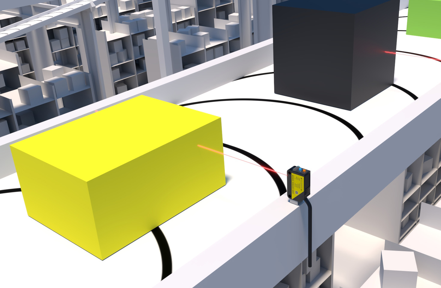
Integration with industrial networks and protocols is increasingly important. Modern interface circuits often include serial communication interfaces (e.g., RS-485, CAN bus) or industrial Ethernet ports to enable seamless connectivity within Industry 4.0 frameworks. Microcontroller-based interfaces offer flexibility, allowing for programmable gain adjustment, digital filtering, and real-time diagnostics. For instance, a laser sensor measuring part dimensions on a conveyor belt might interface with a PLC via a 4-20 mA current loop, providing robust, noise-resistant transmission over distance.
Testing and validation are essential final steps. Engineers should perform bench tests with signal generators and oscilloscopes to verify circuit response under simulated conditions, followed by field trials in actual operational environments. Compliance with industry standards, such as IEC 61000 for EMC, ensures reliability and safety. In summary, designing an effective laser sensor interface circuit requires a holistic approach, balancing electrical performance, environmental robustness, and system integration. By focusing on signal integrity, noise reduction, and adaptability, engineers can unlock the full potential of laser sensing technology, enhancing precision and efficiency in applications ranging from robotics to quality control. As technology evolves, trends like miniaturization and smart sensor interfaces will continue to shape future designs, demanding ongoing innovation in circuit engineering.